
Household garbage vertical burning rotary grate furnace system

A technology for rotating grate and domestic waste, applied in the direction of incinerator, combustion method, combustion type, etc., can solve the problems of uneven distribution, heavy workload, high operating cost, etc., and achieve the effect of improving unevenness and improving work efficiency

Inactive Publication Date: 2013-01-30
陈仲伟
View PDF0 Cites 0 Cited by
  • Summary
  • Abstract
  • Description
  • Claims
  • Application Information

AI Technical Summary

Problems solved by technology

The above-mentioned various forms of incineration devices, some of which require large equipment investment and high operating costs, some of which cannot be burned thoroughly, resulting in new pollution, and some of which require garbage sorting, resulting in a large workload
At present, there is no ideal incinerator that can be popularized and applied.
In addition, the garbage is directly put into the incinerator, so that the garbage is not evenly distributed in the incinerator, so the garbage cannot be fully burned; the slag discharge structure is unreasonable, so that the burning garbage is also treated as waste residue

Method used


Image

  • Household garbage vertical burning rotary grate furnace system
  • Household garbage vertical burning rotary grate furnace system
  • Household garbage vertical burning rotary grate furnace system

Examples


Embodiment Construction

[0026] The purpose, features and advantages of the present invention will be further described with reference to the accompanying drawings in conjunction with the embodiments. Examples will help to understand the present invention, but do not limit the content of the present invention. All deformations that can be directly derived or associated by those skilled in the art from the content disclosed in the present invention should be considered as the protection scope of the present invention.

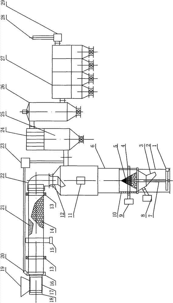
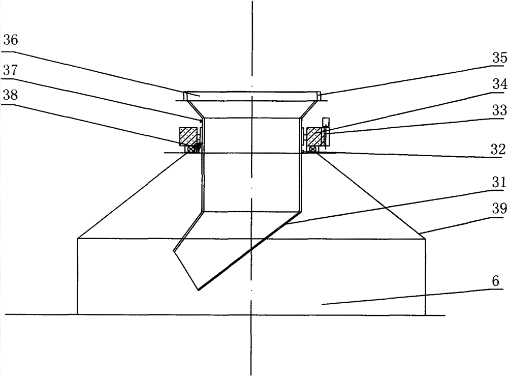
[0027] A rotary grate furnace system for vertical incineration of domestic waste, which includes a discharge transmission device 1, a bracket 2, a slag discharge pipe 3, an annular air pipe 4, a multi-layer tower grate 5, an incinerator main body 6, a transmission column 7, an inlet Fan 8, Roche blower 9, rotating material distribution device 12, garbage feeding dryer 21, cam device 13, feeding transmission device 15, flue gas connection cover 16, feeding outer cylinder 17, feeder 18, f...


PUM


Abstract

The invention relates to a household garbage vertical burning rotary grate furnace system, which comprises a discharge transmission device, a bracket, a slag discharge pipe, an annular air duct, a multilayer tower grate, a burning furnace main body, a transmission upright post, a draft fan, a Roche fan, a rotary feed distribution device, a garbage feed dryer, a cam device, a feed transmission device, a fuel gas connecting hood, a feeding outer cylinder, a feeder, a feeding hopper, a fuel gas circuit pipe, a fuel gas connecting hood, a feed connecting hood and a secondary blower, wherein the bracket supports the burning furnace main body; the lower part of the burning furnace main body is provided with the multilayer tower grate; the lower part of the multilayer tower grate is connected with the slag discharge pipe; the discharge transmission device is connected with the multilayer tower grate through the transmission upright post; the top over of the burning furnace main body is provided with the rotary feed distribution device; the annular air duct is arranged on the burning furnace main body at the position where the multilayer tower grate is arranged; the garbage feed dryer is provided with the cam device and the feed transmission device; a garbage transmission pipe is connected with the rotary feed distribution device through the fuel gas connecting hood; the feeding hopper is connected with the garbage transmission pipe through the feeding outer cylinder and the feeder; the fuel gas circuit pipe is connected with the garbage transmission pipe and the connector of the feeding outer cylinder through the fuel gas connecting hood; and the fuel gas circuit pipe is connected with the gas outlet of the burning furnace main body through the secondary blower.

Description

technical field [0001] The invention relates to a domestic garbage treatment device, in particular to a vertical incineration rotary grate furnace system for domestic garbage. Background technique [0002] At present, there are many domestic and foreign domestic waste disposal methods, and incineration is a more commonly used method. Most of the waste incineration is carried out in the furnace, and the incinerator is divided into two types: vertical and horizontal. In order to fully burn the garbage, various forms of feeding, stirring and ventilation are used, and some fuels are also added to support the combustion. The above-mentioned various forms of incineration devices, some of which require large equipment investment and high operating costs, some of which cannot be burned thoroughly, resulting in new pollution, and some of which require garbage sorting, which requires a large workload. At present, there is no ideal incinerator that can be popularized and applied. In...

Claims


Application Information

Patent Timeline
Patent Type & Authority Patents(China)
IPC IPC(8): F23G5/04F23G5/44F23J15/02
Inventor 陈仲伟
Owner 陈仲伟
Learn More