Eureka AIR delivers breakthrough ideas for toughest innovation challenges, trusted by R&D personnel around the world.

Double-equal pole double-section stator/rotor reluctance generator

A reluctance generator, stator and rotor technology, applied in electrical components, electromechanical devices, DC commutators, etc., can solve the problems of imperfect effect, high energy consumption at low speed, low noise at high speed, etc., to solve the problem of rectifier freewheeling Effects of inefficiency, increased performance and efficiency, increased power density

Inactive Publication Date: 2012-07-25
张世清
View PDF7 Cites 0 Cited by
  • Summary
  • Abstract
  • Description
  • Claims
  • Application Information

AI Technical Summary

Problems solved by technology

However, the effect is not so perfect when the power is medium, the number of poles is small, and the operation is at low speed. Especially after the stator and rotor equipolar technology is adopted to improve the power output, the magnetic poles of the stator and rotor equipolar technology are equivalent to the stator and rotor N, S, N , The S magnetic circuit is in the closed state of the static magnetic poles, so the static resistance is particularly large, resulting in large starting resistance of power generation, large energy consumption at low speed, large noise at low speed, small noise at high speed, large vibration at low speed, and small vibration at high speed

Method used


Image

  • Double-equal pole double-section stator/rotor reluctance generator
  • Double-equal pole double-section stator/rotor reluctance generator
  • Double-equal pole double-section stator/rotor reluctance generator

Examples


Embodiment Construction

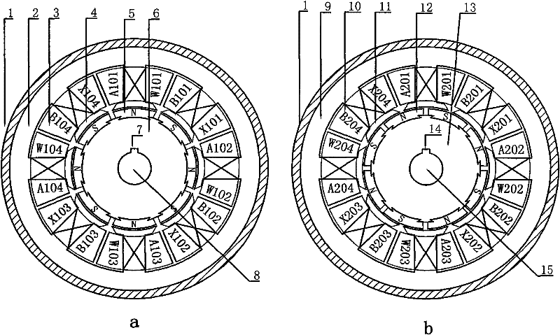
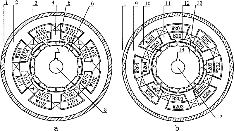
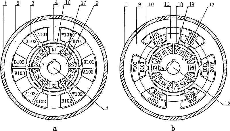
[0045] A double-equal-pole double-segment stator-rotor reluctance generator includes a two-segment stator and a rotor (such as Figure 1 to Figure 9 shown), where figure 1 a, 2a, 3a, and 4a are the schematic cross-sectional views of the first section of the stator and rotor, figure 1 b, 2b, 3b, 4b are the schematic sectional views of the second section of the stator and rotor.

[0046] The stator includes a stator housing 1, a first stator yoke 2, a second stator yoke 9, a first stator armature concentrated winding 3, a second stator armature concentrated winding 10, a first stator pole 4, a second The two-stage stator pole 11 and the frame 43 .

[0047] The number of stator and rotor poles in the two-stage stator and rotor is composed of 2 poles, 4 poles, 6 poles, 8 poles, 10 poles, 12 poles...n poles, and they are all composed of even poles, that is, opposite poles, to adapt to different Rotating speed.

[0048] The two-stage stator with a salient pole structure and the st...


PUM


Abstract

The invention relates to a double-equal pole double-section stator / rotor reluctance generator, comprising two sections of stators and rotors of a salient pole structure or a non-salient-pole structure formed by laminating silicon-steel plates. A stator salient pole is provided with armature concentrated windings or layer windings; the windings are connected in series or in parallel according to the N-N polarity of the armature windings to form a phase, and the windings are connected in series or in parallel according to the S-S polarity of the armature windings to form the other phase; the rotors are equipped with rotating magnetic poles with the same pole number with the stators, and the adjacent pole windings of the rotors are connected in series or in parallel to form a plurality of N and S groups; the rotors can adopt excitation magnetic poles and permanent magnetic poles in different forms and permanent magnetic and electro-magnetic mixed poles, and a rotor excitation device is arranged on a motor shaft; each rotor can be divided into an inner rotor and an outer rotor; and the armature windings can be arranged on the stators or the rotors. In the invention, by adopting an equal-pole-number stator / rotor technology and series / parallel connection dynamic combination of the windings, output voltage can be regulated conveniently, the utilization ratio of the windings is improved, and power density and efficiency of the generator are enhanced.

Description

technical field [0001] The invention belongs to the technical field of generators, and relates to a reluctance generator, in particular to a biequal pole and double-stage stator-rotor reluctance generator. Background technique [0002] The existing switched reluctance motor (SRM) is a motor with a double salient pole structure. Its stator and rotor are laminated with ordinary silicon steel sheets to form a salient pole type. Concentrated windings are wound on the stator poles, while the rotor has no windings. There is also no permanent magnet; the motor can be divided into single-phase, two-phase, three-phase, four-phase and multi-phase switched reluctance motors according to the number of phases, and also has three-phase 6 / 4 pole structure, 12 / 8 pole structure and four-phase Most of them have 8 / 6 pole structure; the advantages of switched reluctance motor are: simple structure, easy to manufacture, high operating efficiency, high power factor, small starting current, large ...

Claims


Application Information

Patent Timeline
Patent Type & Authority Patents(China)
IPC IPC(8): H02K23/40H02K23/04H02K16/00H02K23/26
Inventor 张世清张红梅
Owner 张世清
Why Eureka
Eureka Blog
Learn More