
Device for generating circular oscillation or directional oscillation

A kind of equipment, circular technology, applied in the field of equipment that generates circular vibration or directional vibration, can solve the problem that there is no room for the unbalanced main body, and achieve simple and fast coupling stability, reduced manufacturing cost, and high compactness Effect

Inactive Publication Date: 2011-02-02
BOMAG
View PDF6 Cites 1 Cited by
  • Summary
  • Abstract
  • Description
  • Claims
  • Application Information

AI Technical Summary

Problems solved by technology

[0004] Furthermore, the vibration exciter described in DE 2736264 A1 has the disadvantage that there is no latitude for the construction of the unbalanced bodies, since there are always only two unbalanced bodies per axis of rotation

Method used


Image

  • Device for generating circular oscillation or directional oscillation
  • Device for generating circular oscillation or directional oscillation
  • Device for generating circular oscillation or directional oscillation

Examples


Embodiment Construction

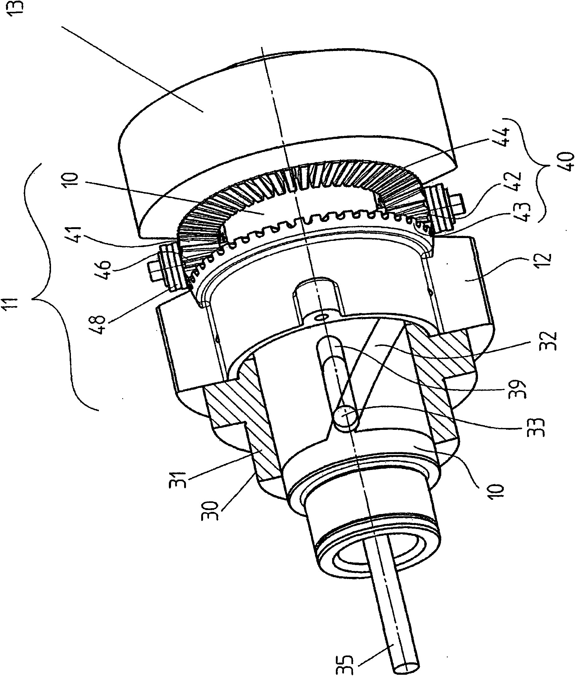
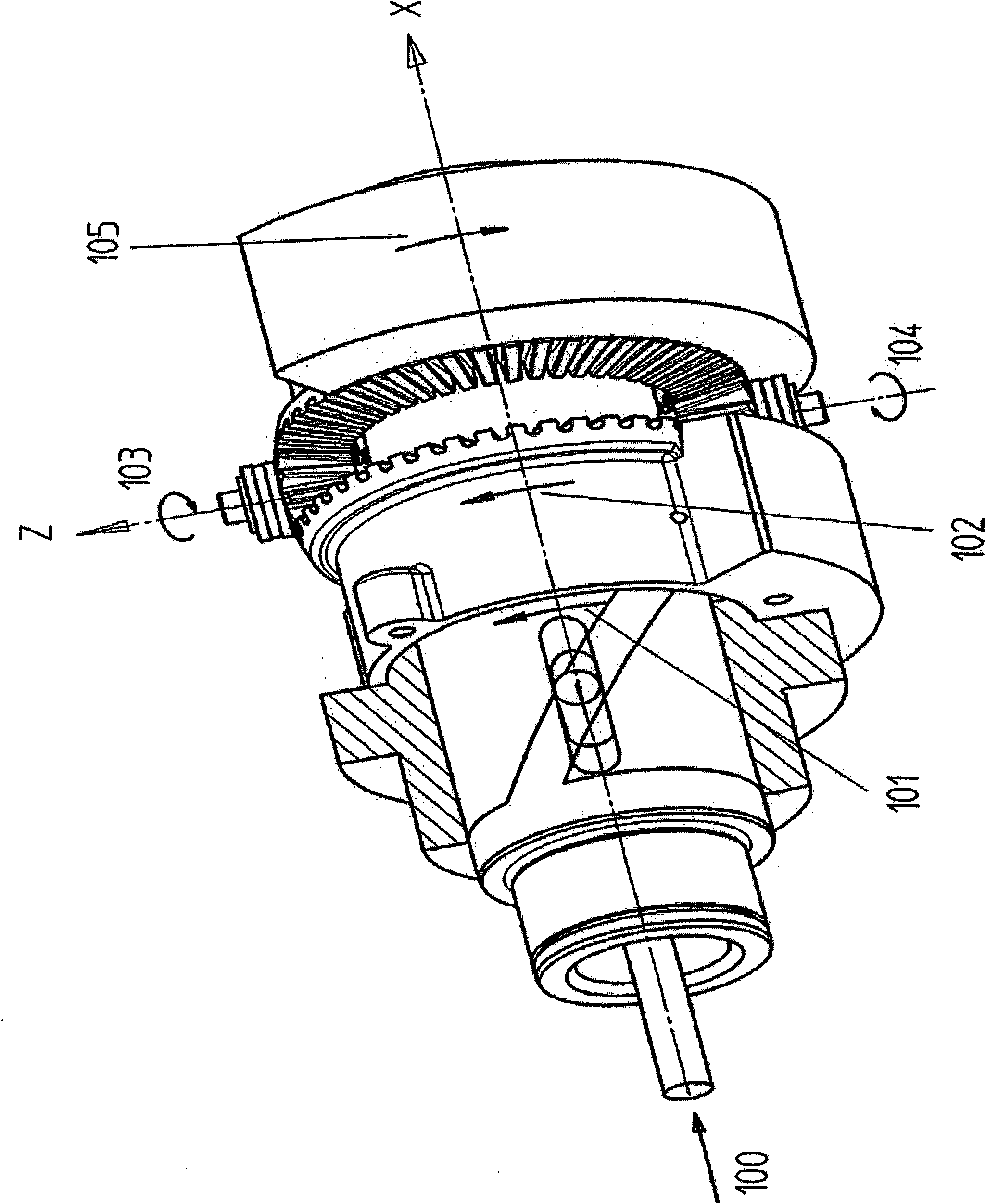
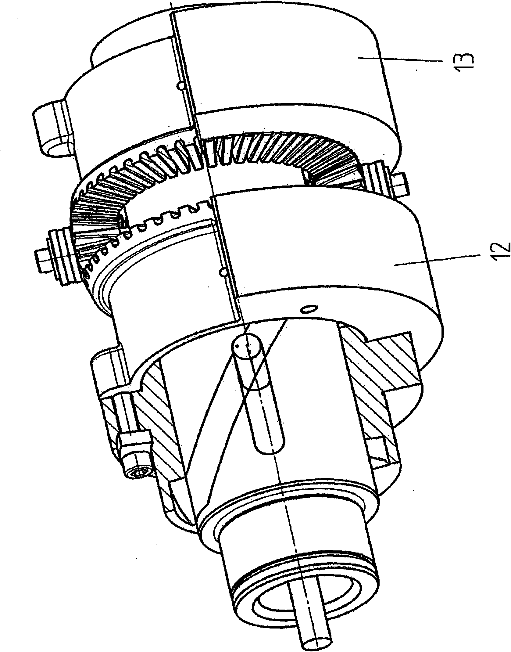
[0037]figure 1 A first unbalanced weight pair 11 of a first spindle 10 is shown, said first unbalanced weight pair 11 having unbalanced weights 12 , 13 . Located between the unbalanced weights 12 , 13 is a coupling 40 having two crown wheels 43 , 44 and a transmission medium 46 , in particular pinions 41 , 42 . The pinions 41 , 42 are symmetrical relative to the axis of rotation of the main shaft 10 and offset by 180°, they are rotatable on the transmission medium carrier 45 . Furthermore, axial bearings 48 are known and serve to absorb the centrifugal forces generated by the pinions 41 , 42 .

[0038] The adjusting unit 30 has an adjusting sleeve 31 , which is fixedly connected to the first unbalanced weight 12 with axial locking, for example via screws 36 , in a rotationally fixed manner. The inner wall of the adjustment sleeve 31 is provided with two helical grooves 32 offset by 180°. Engaging in the helical groove 32 is an adjustment pin 33 which is guided in an oblong h...


PUM


Abstract

A device for generating a circular oscillation or a directional oscillation is provided. The device provides a circular oscillation, or, if two parallel main shafts rotating synchronously in opposite directions are coupled, a directional oscillation, each main shaft having unbalance weights and a coupling between the unbalance weights and the oscillation amplitude of the exciter force per main shaft being continuously adjustable between a minimum value and a maximum value using an adjustment unit via the relative rotation of the unbalance weights toward or away from one another. The device includes unbalance weights that are mounted on the main shaft so they are rotatable thereon, and the coupling comprises a transmission medium connected rotationally fixed to the main shaft, which is composed so that it acts as a driver on the unbalance weights and also causes a pivoting of the unbalance weights in opposite directions upon the adjustment of the oscillation amplitude of the exciter force.

Description

technical field [0001] The present invention relates to a device for generating circular or directional vibrations as described in the preamble of the independent claim. Such devices are used in particular in construction machines for soil compaction. Typically, two spindles are used that sit in parallel within the same housing, each with an unbalanced weight. To generate directional vibration, the main shaft is set to rotate simultaneously and in opposite directions using, for example, direct meshing spur gears. In order to continuously adjust the vibration amplitude of the exciter force, the angle of the unbalanced weights is changed, so that the effective exciter force composed of the centrifugal force of each unbalanced weight continuously increases or decreases within a predetermined range. Background technique [0002] The vibration amplitude and / or the exciter force are usually adjusted using a shaft on which the unbalance weights are seated, which on the one hand a...

Claims


Application Information

Patent Timeline
Patent Type & Authority Applications(China)
IPC IPC(8): B06B1/16E02D3/074
CPCB06B1/166Y10T74/18344
Inventor H-W·屈藤
Owner BOMAG
Learn More