
Apparatus for the separation of plasma

An equipment and plasma technology, applied in filtration separation, separation method, semi-permeable membrane separation, etc., can solve the problems of no filling, no usable amount, different liquid filling channel rates, etc., and achieve the effect of simple structure

Inactive Publication Date: 2011-01-26
BOEHRINGER INGELHEIM MICROPARTS
View PDF2 Cites 7 Cited by
  • Summary
  • Abstract
  • Description
  • Claims
  • Application Information

AI Technical Summary

Problems solved by technology

The disadvantage is that the channels are filled with sample fluid in the form of plasma at varying rates, or not at all
Therefore a consistent liquid front cannot be obtained
This is problematic for analysis because there is no definite amount available at the same time, e.g. dry chemicals etc. cannot be simultaneously dissolved in the sample liquid in desired or necessary amounts

Method used


Image

  • Apparatus for the separation of plasma
  • Apparatus for the separation of plasma
  • Apparatus for the separation of plasma

Examples


Embodiment Construction

[0031] In the drawings, the same reference numerals are used for the same or similar parts, but corresponding or comparable properties and advantages can be realized even without repeating the related description.

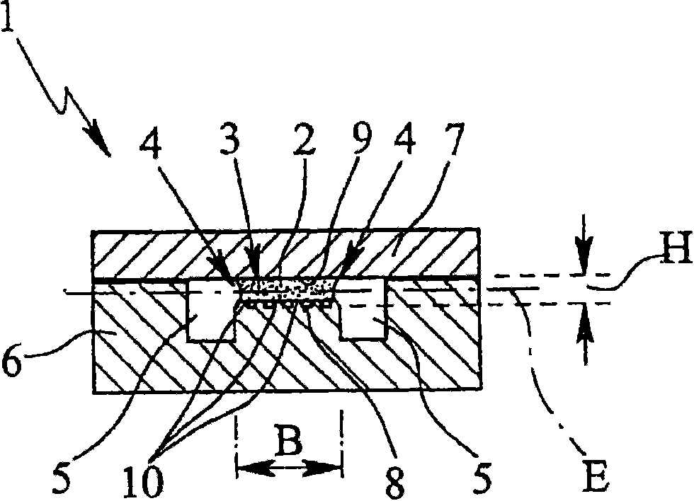
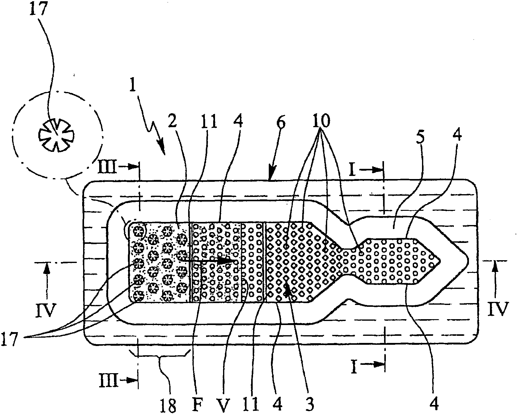
[0032] figure 1 In a schematic section, a first embodiment of the proposed device 1 for absorbing and / or analyzing a sample liquid 2 (in particular blood plasma or the like) is shown. The device 1 has a channel 3 which draws sample liquid by capillary force. Channel 3 is open at least on one narrow or longitudinal side 4, in figure 1 In the exemplary embodiment shown, both narrow or longitudinal sides 4 are open.

[0033] Finally, adjoining the open side 4 is a recess 5 , which in the embodiment shown is preferably groove or groove-shaped.

[0034] Thus, a lateral liquid barrier (and thus a flow obstacle that cannot be overcome by capillary forces) of the sample liquid 2 is formed in the channel 3, and the sample liquid 2 can follow the open side 4 in the channe...


PUM

PropertyMeasurementUnit
Heightaaaaaaaaaa
Widthaaaaaaaaaa

Abstract

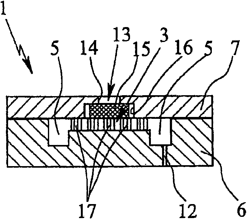
The invention relates to an apparatus for separating blood, more particularly an apparatus (1) for absorbing blood (19) and separating blood components, e.g. blood plasma, as a sample liquid (2). Said apparatus (1) comprises a feeding device (13) for absorbing the blood (2), a device (15) for separating blood components as a sample liquid (2), a duct which preferably absorbs the sample liquid (2) exclusively by means of capillary forces, and a device for filling the duct (3) with sample liquid (2) in an inlet or feeding zone (18) of the duct (3). The separating device (15), in particular a membrane, is curved, especially convexly shaped, and the apex of said curved, especially convex shape projects into the filling device.

Description

technical field [0001] The present invention relates to a device for absorbing blood and separating blood components such as plasma as a sample liquid. [0002] The present invention relates to microfluidic systems or devices. The following statements apply to equipment in which capillary forces play a role and are especially important for operation. Background technique [0003] Apparatus for separating plasma from blood are described in US4906439 and WO01 / 24931A1, in each case a plurality of separate trough-like or capillary-like channels are provided to receive and transport the plasma. The disadvantage is that the channels are filled with sample liquid in the form of plasma at varying rates, or not at all. Therefore a consistent liquid front cannot be obtained. This is problematic for analysis because there is no definite amount available at the same time, eg dry chemicals etc. cannot be simultaneously dissolved in the sample liquid in desired or necessary amounts. ...

Claims


Application Information

Patent Timeline
IPC IPC(8): B01L3/00
CPCB01L2300/0681G01N33/491B01L2400/0406B01L2300/0864B01L3/502715B01L3/502753B01D63/08B01D2201/44B01D29/014B01D61/18B01D63/087B01D2201/0415B01D63/088B01D29/05
Inventor 格特·布兰肯斯滕霍尔格·巴托斯拉尔夫-彼得·彼得斯克里斯琴·舍恩
Owner BOEHRINGER INGELHEIM MICROPARTS
Learn More