
Lamp holder of lamps in different types

A lamp holder and lamp type technology, which is applied in the direction of headlights, parts of lighting devices, lighting and heating equipment, etc., can solve the problems of high production cost and increase of total cost, etc.

Active Publication Date: 2011-01-26
ZKW集团有限公司
View PDF4 Cites 2 Cited by
  • Summary
  • Abstract
  • Description
  • Claims
  • Application Information

AI Technical Summary

Problems solved by technology

This leads to higher production costs on the one hand, and on the other hand, different lamp holders must be stored and supplied to the manufacturer separately, increasing the total cost

Method used


Image

  • Lamp holder of lamps in different types
  • Lamp holder of lamps in different types
  • Lamp holder of lamps in different types

Examples


Embodiment Construction

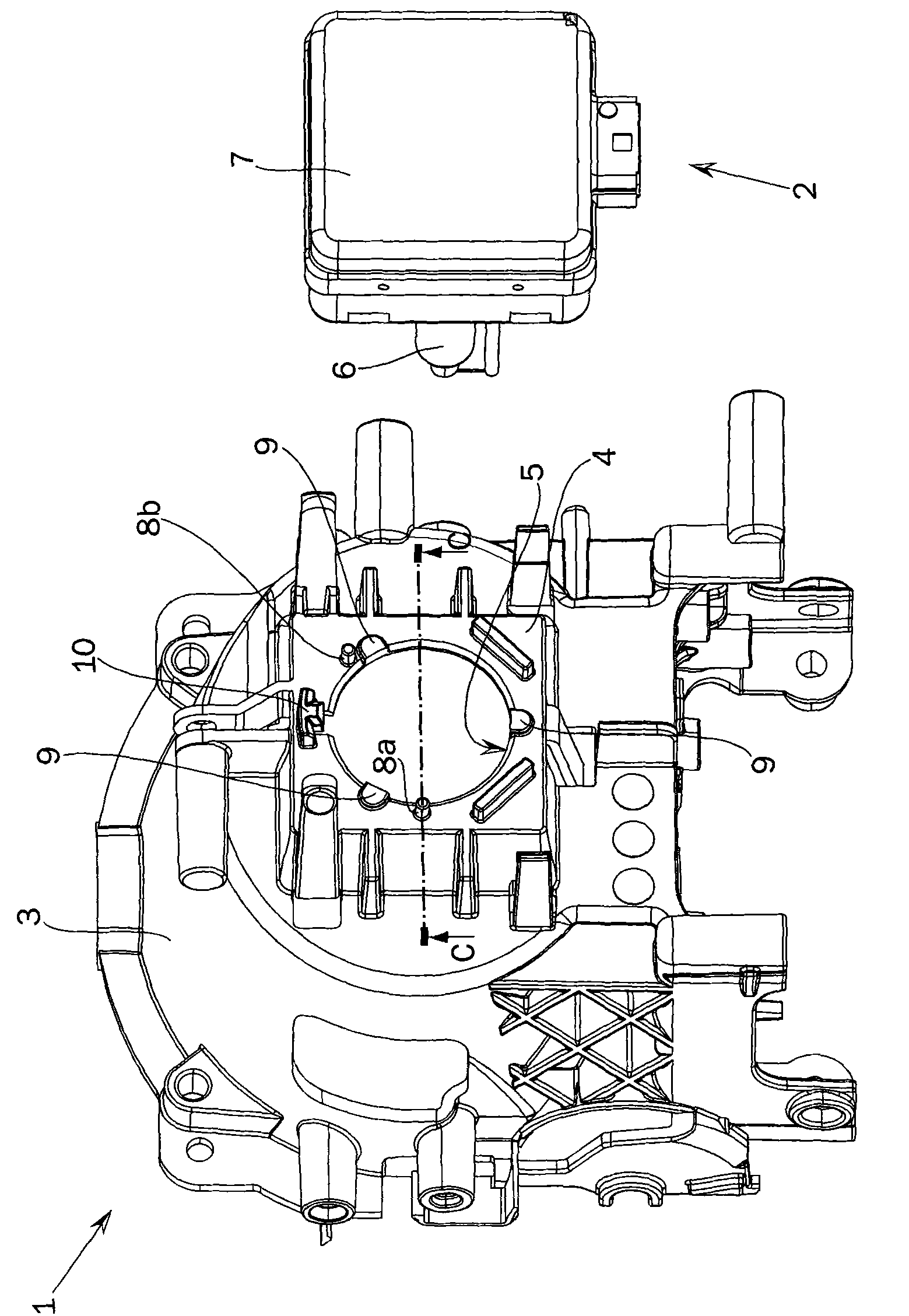
[0027] figure 1 It is a perspective view of a vehicle headlamp 1 and a lamp 2 separated therefrom before installation. Without limiting the invention, only the parts of the vehicle headlamp 1 and the lamp 2 which are necessary for understanding the invention are explained below.

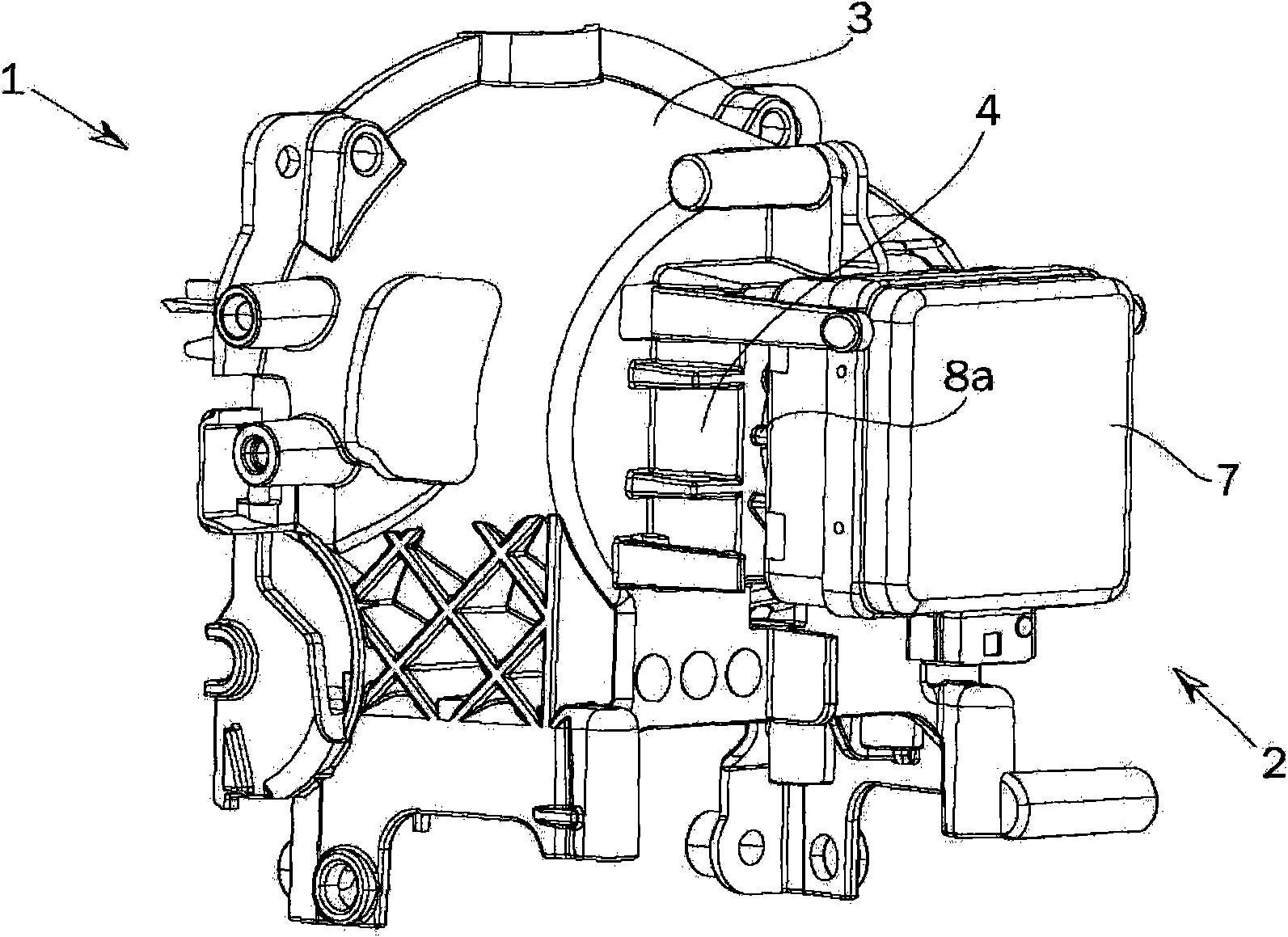
[0028] figure 1 The vehicle headlamp 1 shown in includes a reflector adapter 3 on which a lamp holder 4 is placed. The lamp holder 4 can be an integral part of the reflector adapter 3 or a separate part.

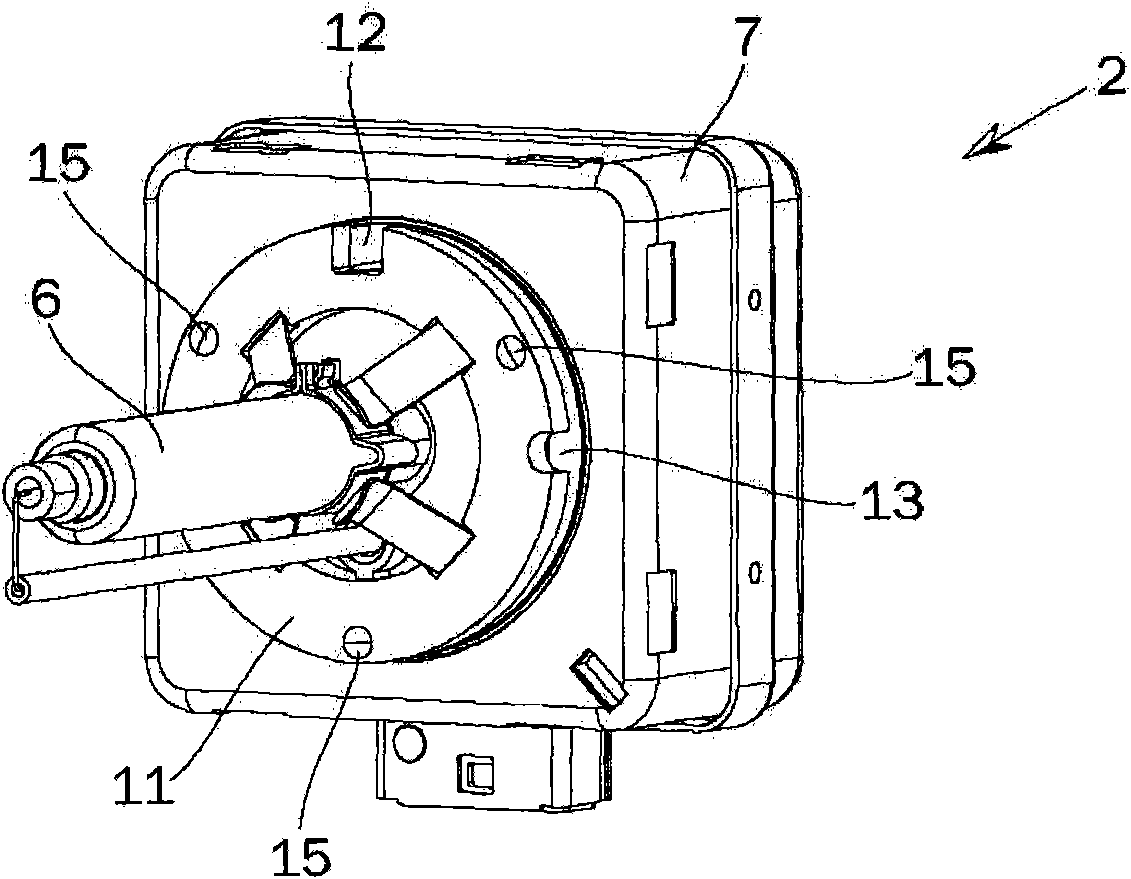
[0029] The lamp 2 generally comprises a light source 6 and an actuator 7 forming a connection assembly.

[0030] An opening 5 through which the light source 6 of the lamp 2 passes is formed in the reflector fitting 3 (and the reflector not shown in the figure) and the lamp socket 4 . After installation (see figure 2 ), the light source 6 of the lamp 2 is derived from the opening 5, and the starter 7 passes through the lamp holder 11 (refer to image 3 ) on the lamp holder 4. The reference p...


PUM


Abstract

The invention relates to a lamp holder (4) of a vehicle head lamp (1), comprising coding elements (8a, 8b) which definitely define the type of the used lamp, wherein the movable coding elements (8a, 8b) of at least two types of lamps are provided so as to definitely appoint the type of the lamp for the lamp holder (4) by moving the unnecessary coding elements (8a, 8b).

Description

technical field [0001] The invention relates to a lamp holder for a vehicle headlamp comprising a coding element for unambiguously defining the type of lamp used. Background technique [0002] When installing a lamp to the lamp socket (socket) of a vehicle's headlamp, it is necessary to ensure that the correct lamp is installed. This depends inter alia on compatibility between lamp and reflector. Using the wrong light source can sometimes violate legal regulations or cause damage to components, for example due to overheating. [0003] In many cases it is ensured that the correct type of lamp is installed by attaching a coding device to the socket which cooperates with a corresponding device placed on the lamp. These coding elements comprise, for example, lugs that mate with corresponding holes in the lamp. By arranging the pins according to the type of lamp required, it is ensured that the correct lamp is installed. [0004] Many reflectors are very specific designed for...

Claims


Application Information

Patent Timeline
Patent Type & Authority Applications(China)
IPC IPC(8): F21V21/00F21W101/10F21W107/00
CPCF21S48/1186F21S48/1104F21S41/17F21S41/19
Inventor 斯蒂芬·斯吉布劳尔
Owner ZKW集团有限公司
Learn More