Supercharge Your Innovation With Domain-Expert AI Agents!

Guide beam type bridge-erecting machine capable of performing variable-span erection

A bridge erecting machine and guide beam type technology, applied in the direction of erecting/assembling bridges, bridges, bridge construction, etc., can solve the problems of poor adaptability, large cross-sectional size of the bridge erecting machine, and inability to change the span of box girder construction, etc. It is easy to achieve. The effect of realization and operation

Active Publication Date: 2012-01-25
SUZHOU DAFANG SPECIAL VEHICLE
View PDF0 Cites 0 Cited by
  • Summary
  • Abstract
  • Description
  • Claims
  • Application Information

AI Technical Summary

Problems solved by technology

[0003] The existing bridge erecting machines generally have the following defects: the cross-sectional size of the bridge erecting machine is large, and it needs to be dismantled when the bridge erecting site is transferred or when passing through the tunnel; , it is not possible to erect 24m or 20m variable-span box girders in the basket arch bridge or tunnel bridge section; the passing process is complicated; the longitudinal stability is poor

Method used


Image

  • Guide beam type bridge-erecting machine capable of performing variable-span erection
  • Guide beam type bridge-erecting machine capable of performing variable-span erection
  • Guide beam type bridge-erecting machine capable of performing variable-span erection

Examples


Embodiment Construction

[0027] Below in conjunction with accompanying drawing and specific embodiment the present invention is described in further detail:

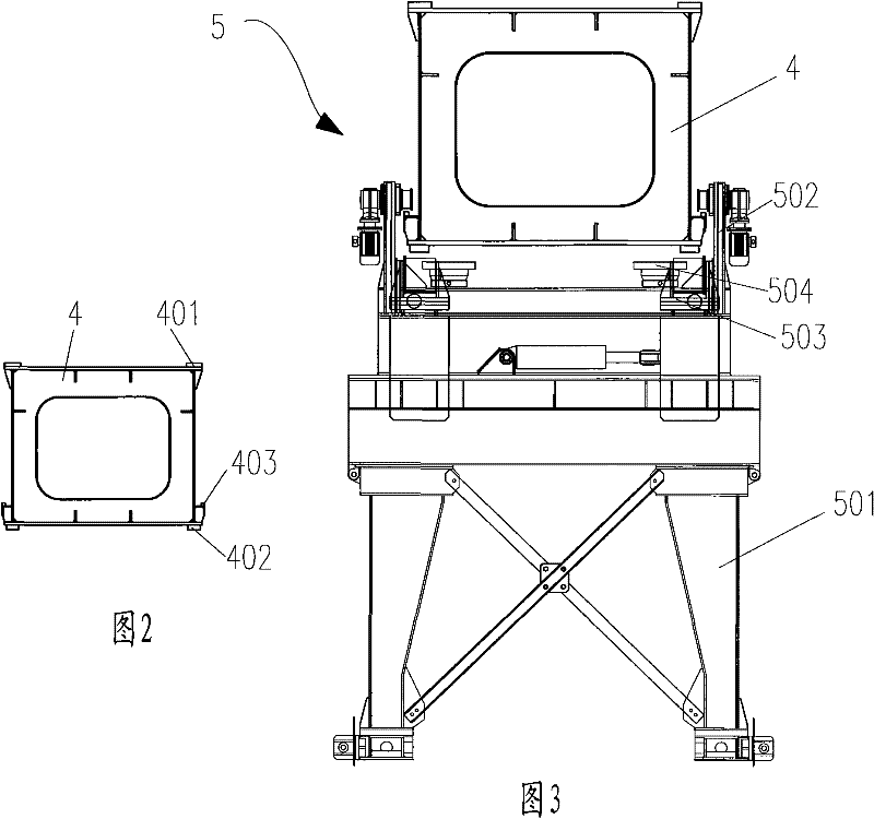
[0028] See attached figure 1 The shown guide girder bridge erecting machine includes a main girder 1, a main girder front leg 2 installed at the front end of the main girder 1, a main girder rear leg 3 installed at the rear end of the main girder, and a The lower guide beam 4, the lower guide beam front leg 5 installed at the front end of the lower guide beam, the lower guide beam alignment leg 6 installed at the lower guide beam rear end, the movable leg 7 movably arranged on the lower guide beam 4, Crane 8 and spreader 9 are also movable on the main girder 1 . The movable outrigger 7 is a structure that can be stretched up and down. It can be used as a fulcrum supported by the lower guide beam 4 on the bridge surface. a fulcrum.

[0029] Such as Figure 7 As shown, the main girder 1 is in the form of a double-girder box, and each set of ma...


PUM


Abstract

The invention relates to a guide beam type bridge-erecting machine. The guide beam type bridge-erecting machine comprises a girder and a lower guide beam, wherein a girder front supporting leg and a girder rear supporting leg are arranged at the front end and the rear end of the girder respectively; a lower guide beam front supporting leg, a moveable supporting leg and a lower guide beam para-position supporting leg are arranged on the lower bottom surface of the lower guide beam from front to back; the moveable supporting leg has an up-and-down telescopic structure; the moveable supporting leg can support the lower guide beam and can also support the girder; a crown block beam is arranged on the girder; a crane crown block is arranged on the crown block beam; a longitudinally-moveable oil cylinder is arranged on the girder; a piston rod of the longitudinally-moveable oil cylinder is connected with the crown block beam; the crown block beam can move along the girder back and forth under the action of the longitudinally-moveable oil cylinder; the lower guide beam is provided with a second guide rail by which the moveable supporting leg can move along the lower guide beam back and forth; and when the bridge-erecting machine performs variable-span erection by changing a span, the crown block beam moves along the girder back and forth and the moveable supporting leg moves along the second guide rail on the lower guide beam back and forth. The variable-span erection of the bridge-erecting machine can be realized by the position change of the moveable supporting leg of the lowerguide beam and the crane crown block of the bridge-erecting machine easily.

Description

technical field [0001] The invention relates to a guide beam type bridge erecting machine, in particular to a guide beam type bridge erection machine with variable span erection. Background technique [0002] According to my country's "Medium and Long-Term Railway Network Planning", there are about 12,000 kilometers of passenger dedicated lines and high-speed railways currently under construction and about to be constructed, and bridges account for more than 50% of the lines. Among them, the Beijing-Shanghai high-speed railway bridge accounts for about 80%. The main girder types of these bridges are 32m, 24m, and 20m prefabricated box girders with full holes. The heaviest 32m double-line full hole box girder weighs about 900 tons. Features such as span and curve erection. The Beijing-Shanghai high-speed railway needs to cross the Tilan arch bridge to erect box girders. Some passenger dedicated lines are located in hills and mountains, and bridge erecting machines need to p...

Claims


Application Information

Patent Timeline
Patent Type & Authority Patents(China)
IPC IPC(8): E01D21/00
Inventor 熊春奎巩立辉
Owner SUZHOU DAFANG SPECIAL VEHICLE
Features
  • R&D
  • Intellectual Property
  • Life Sciences
  • Materials
  • Tech Scout
  • Unparalleled Data Quality
  • Higher Quality Content
  • 60% Fewer Hallucinations
Learn More