Preprocessing technology employed multi-carrier signal peak clipping device and method

A multi-carrier signal, carrier signal technology, applied in pulse processing, signal channel, pulse technology and other directions, can solve the problems of the deterioration of various indicators of weak signal systems, the deterioration of multi-carrier signal quality, and the large noise signal interference, and the increase Application prospects and use effects, no need for delay alignment requirements, and the effect of reducing mutual interference

Inactive Publication Date: 2005-11-30
南通市飞宇石油科技开发有限公司
View PDF3 Cites 16 Cited by
  • Summary
  • Abstract
  • Description
  • Claims
  • Application Information

AI Technical Summary

Problems solved by technology

Although this method proposes a method with better performance based on various peak clipping methods, there are still four defects in this method: First, because all peak clipping in this method is completed based on multi-carrier signals, in In practice, if the power of multiple carriers is very unbalanced, some protocols require a dynamic of 30dB. At this time, the noise signal of the peak clipping will greatly interfere with the weak useful signal, resulting in serious deterioration of the indicators of the weak signal system; secondly, the method It is necessary to complete the extraction and processing of the noise signal and add it to the delayed original signal, which requires precise time synchronization and puts forward high requirements for real-time performance. ) increases the greater difficulty; again, the method of noise processing in this method is more effective for continuous multiple carrier processing, but if multiple carriers are discontinuously allocated, the noise processing method will inevitably cause the adjacent channel leakage index to be unsatisfied System requirements, so the use of this method is limited; finally, because this method is only based on multi-carrier peak clipping, the peak clipping capability is limited, and excessive peak clipping leads to the overall deterioration of the quality of the entire multi-carrier signal

Method used


Image

  • Preprocessing technology employed multi-carrier signal peak clipping device and method
  • Preprocessing technology employed multi-carrier signal peak clipping device and method
  • Preprocessing technology employed multi-carrier signal peak clipping device and method

Examples


Embodiment Construction

[0058] In order to deeply understand the present invention, the present invention will be described in detail below in conjunction with the accompanying drawings and specific embodiments.

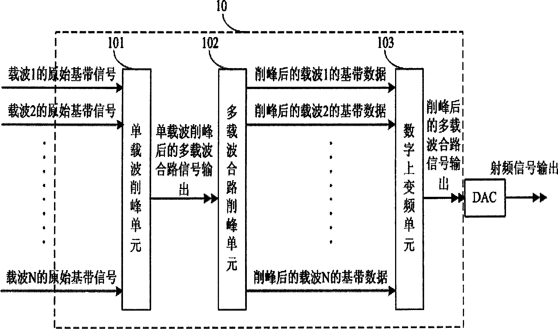
[0059] The basic structure of the multi-carrier signal peak clipping device adopting preprocessing technology in the present invention is as follows: figure 1 shown, from figure 1 It can be seen from the figure that the multi-carrier peak clipping device 10 is composed of a single carrier peak clipping unit 101 , a multi-carrier combined peak clipping unit 102 , and a digital up-conversion unit 103 .

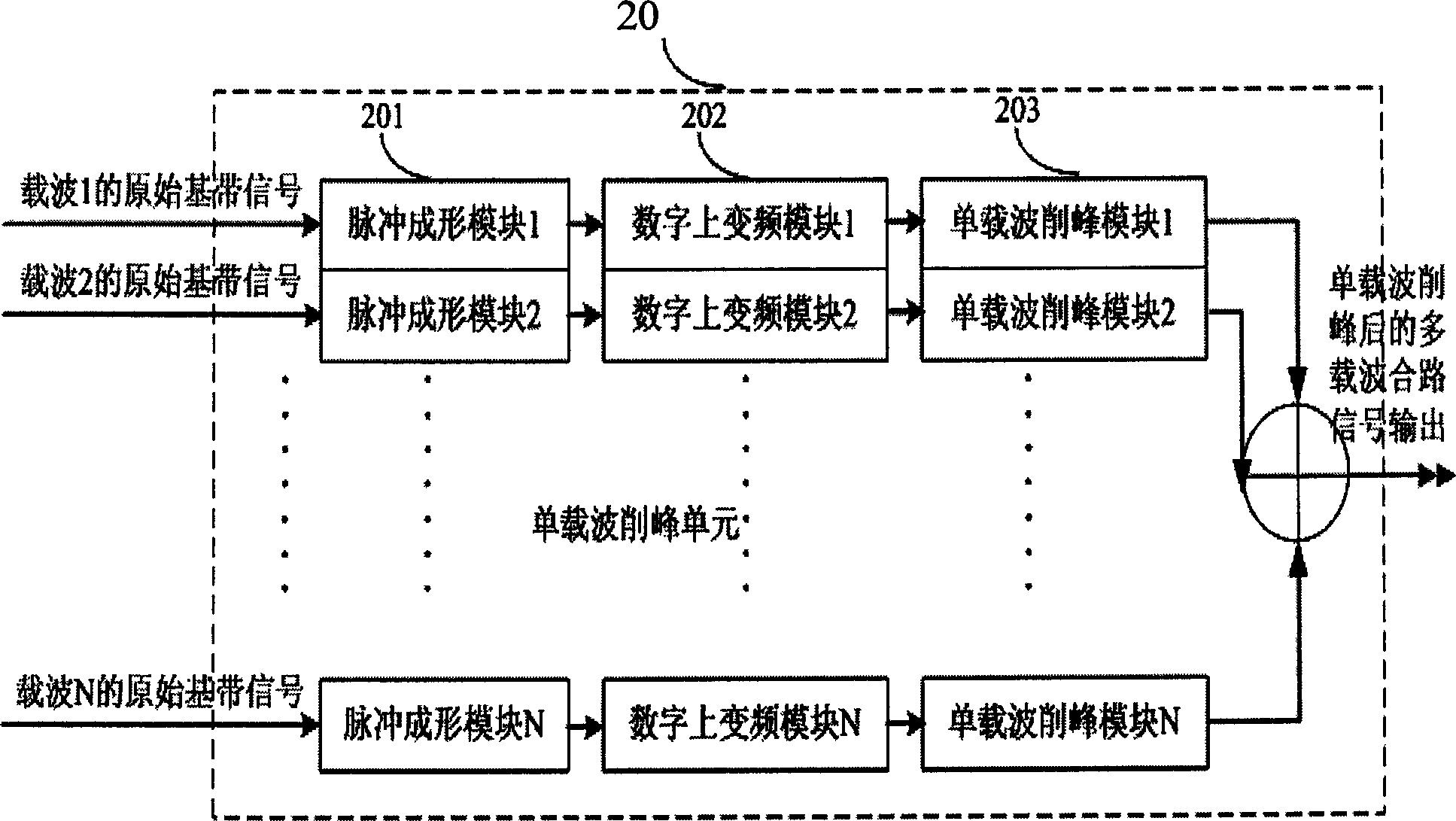
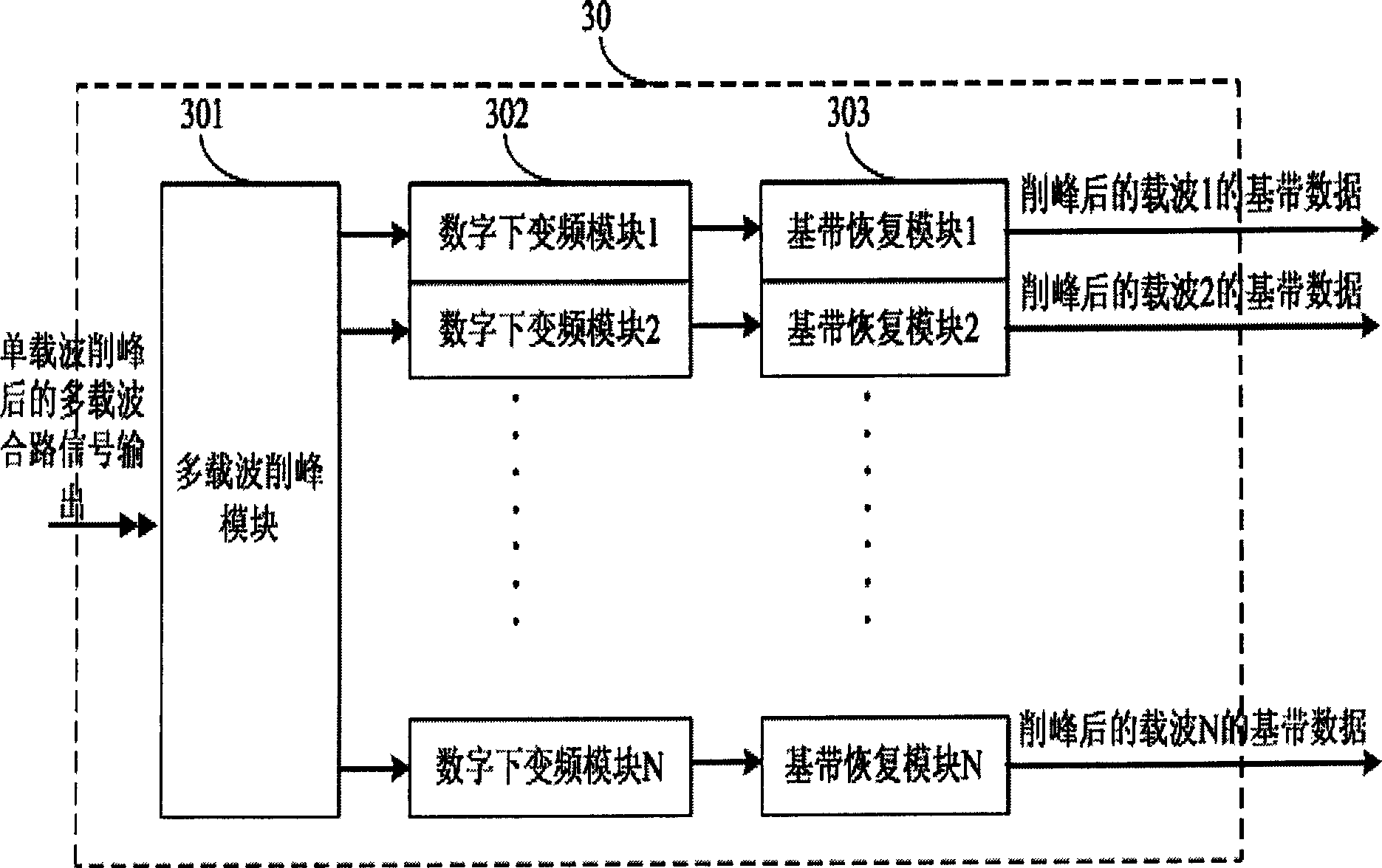
[0060] Among them, the single-carrier peak-shaving unit 101 is used to perform root-raised cosine shaping filtering on the baseband signals of each input carrier, and then perform single-carrier limiting and peak-shaving after digital up-conversion, and combine to generate multi-carriers after single-carrier peak-shaving Combined signal; the multi-carrier combined peak-shaving unit 102 is us...


PUM


Abstract

This invention discloses one multi-wave signal peak chopping device by pre-processing technique, which comprises the following parts: single wave peak chopping unit to receive the base band signal for cosine shaping filtering, digital frequency and single wave peak chopping; then merging the signals into multi-wave signals; multi-wave peak chopping unit to receive the multi-wave signals for peak chopping, digital down frequency and base signal restoring; digital upper frequency unit to receive the base band signals for cosine shaping and filtering to form the multi-wave merging signal.

Description

technical field [0001] The invention relates to the signal processing field of a multi-carrier communication system, in particular to a multi-carrier signal peak clipping device and method using preprocessing technology. Background technique [0002] With the development of communication technology, mobile communication has penetrated into thousands of households, and the demand for system capacity is increasing day by day. At the same time, the voice service can no longer meet the growing demand of people. It is urgent and practical to provide high-quality data service. [0003] In this context, time-division multiple access, code-division multiple access, and space-division multiple access technologies are introduced, but increasing frequency resources is still the most fundamental means of capacity expansion. Therefore, various communication systems such as WCDMA system, CDMA2000 system, TD-SCDMA system, etc., all need multiple carrier frequencies to increase the system c...

Claims


Application Information

Patent Timeline
IPC IPC(8): H03K5/1252
Inventor 王斌肖炼斌刘虎
Owner 南通市飞宇石油科技开发有限公司
Why Eureka
Try Eureka