
Secondary ejecting mechanism of improved type invertedly-buckled bottle cap plastic injection mold

An injection mold and secondary ejection technology, which is applied to household appliances, other household appliances, household components, etc., can solve the problems of increased production cost, long production cycle and low efficiency.

Active Publication Date: 2011-01-26
浙江西诺模具有限公司
View PDF8 Cites 6 Cited by
  • Summary
  • Abstract
  • Description
  • Claims
  • Application Information

AI Technical Summary

Problems solved by technology

Although this mechanism realizes the demoulding of the plastic cover with an undercut without manual operation, since the two ejector plates are driven by the oil cylinder, the structure is relatively complicated, and the mold must be opened before the demoulding can be performed, and the production cycle Long, low efficiency, and more importantly, equip the two oil cylinders with control devices to make the two oil cylinders work in an orderly manner, and the production cost is greatly increased

Method used


Image

  • Secondary ejecting mechanism of improved type invertedly-buckled bottle cap plastic injection mold
  • Secondary ejecting mechanism of improved type invertedly-buckled bottle cap plastic injection mold
  • Secondary ejecting mechanism of improved type invertedly-buckled bottle cap plastic injection mold

Examples


Embodiment Construction

[0016] Embodiments of the present invention will be further described below in conjunction with the accompanying drawings:

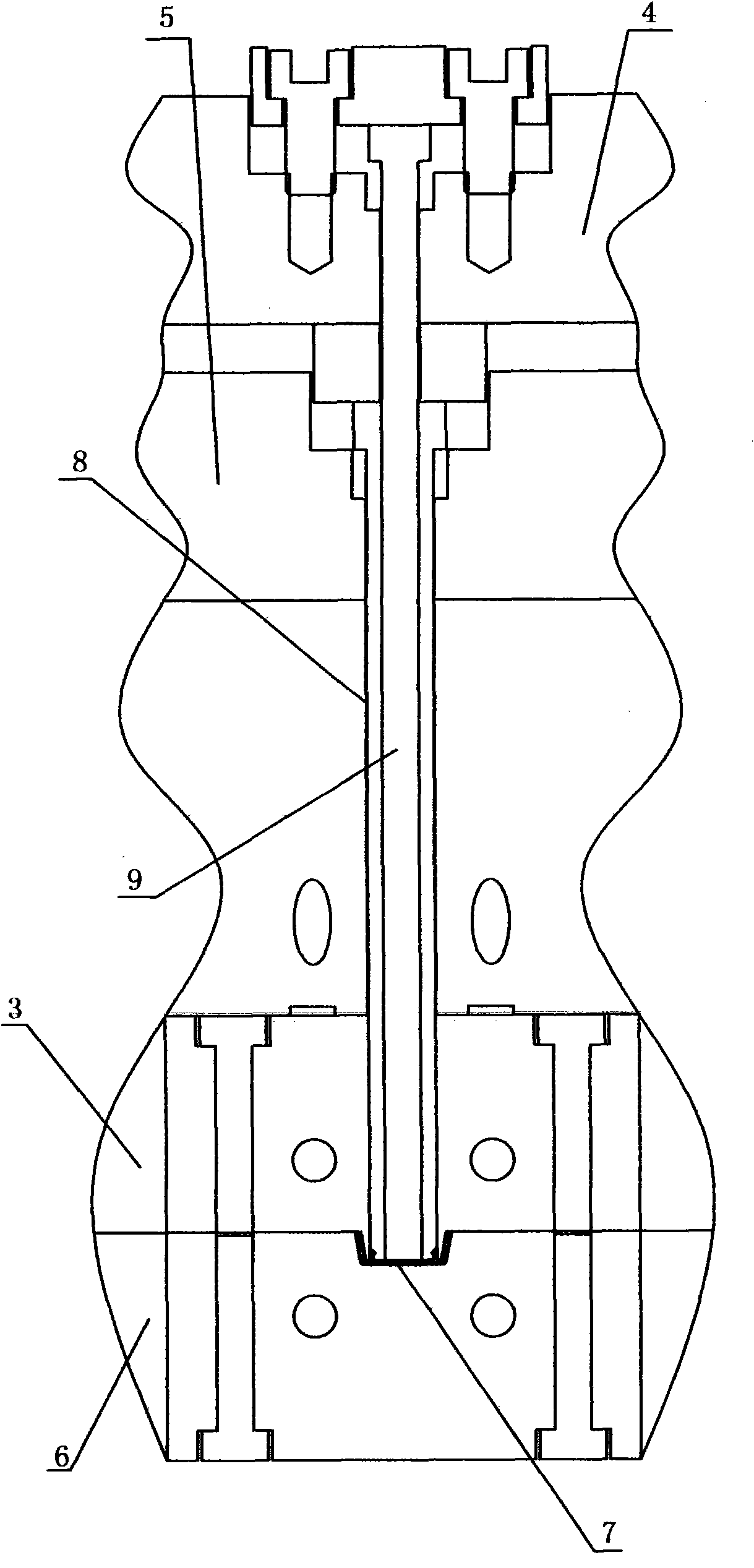
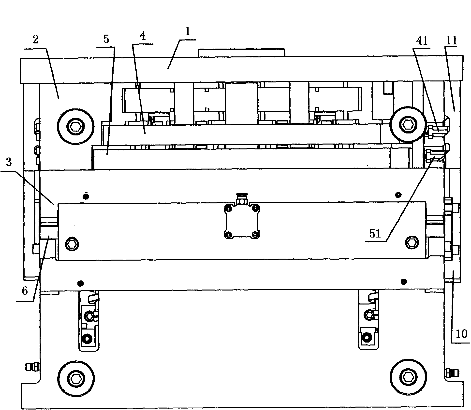
[0017] Such as Figure 1-8 As shown, the secondary ejection mechanism of the improved inverted bottle cap injection mold includes a fixed mold 3 and a movable mold 6, a mold cavity is formed between the fixed mold 3 and the movable mold 6, and the fixed mold 3 is installed through the mold foot 2 On the fixed formwork 1, between the fixed formwork 3 and the fixed formwork 1, there are push tube thimble plate 5 and push tube core thimble plate 4, push tube 8 is installed on the push tube thimble plate 5, and push tube core thimble plate 4 is installed Push tube core 9, wherein the push tube core 9 is located in the push tube 8, the position of the push tube 8 is matched with the mold cavity, and it is characterized in that the push tube core thimble plate 5 and the push tube core thimble plate 4 are made of The drag hook mechanism is driven, and the drag...


PUM


Abstract

The invention relates to a secondary ejecting mechanism of an improved type invertedly-buckled bottle cap plastic injection mold, which comprises a fixed mold and a movable mold, wherein an ejector sleeve needle ejecting plate and an ejector sleeve core needle ejecting plate are arranged between the fixed mold and a fixed mold plate; an ejector sleeve is installed on the ejector sleeve needle ejecting plate; an ejector sleeve core is installed on the ejector sleeve core needle ejecting plate; the ejector sleeve core is positioned in the ejector sleeve; the ejector sleeve needle ejecting plateand the ejector sleeve core needle ejecting plate are driven by a hook mechanism; the hook mechanism comprises a first sliding block, a second sliding block, a guide frame which is fixed on the fixedmold plate and a hook which is positioned in the guide frame; the other end of the hook is fixed on the movable mold; a first sliding guide groove and a second sliding guide groove are arranged on the guide frame; the lower walls of the two sliding guide grooves are both slopes; springs are both arranged between the two sliding blocks and the needle ejecting plates; a first convex block and a second convex block are arranged on the hook; the first convex block drives the first sliding block and is matched with the first sliding guide groove; the second convex block drives the second sliding block and is matched with the second sliding guide groove; and the thickness of the second convex block is larger than the thickness of the first convex block.

Description

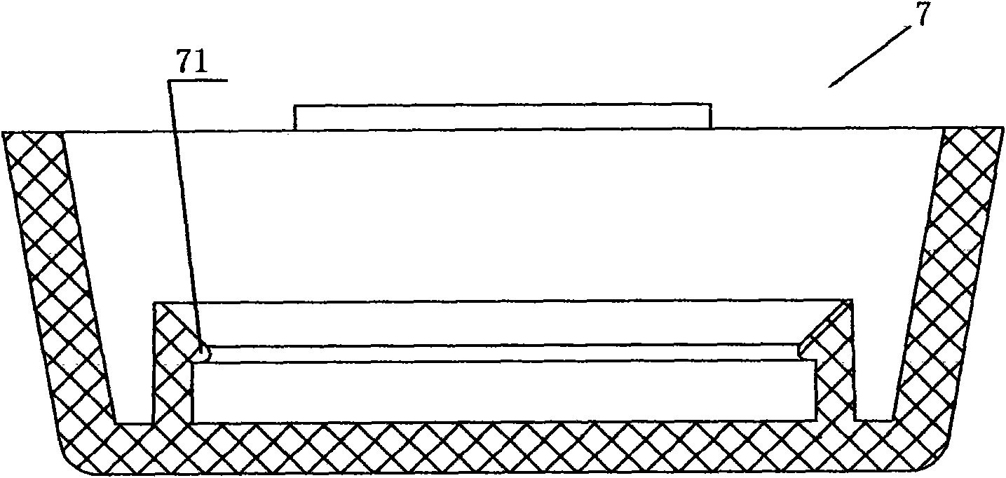
technical field [0001] The invention relates to an improved secondary ejection mechanism of an injection mold for an inverted bottle cap, which belongs to the technical field of plastic machinery. Background technique [0002] Such as image 3 As shown, the plastic cover 7 with an undercut 71 is quite common in daily life. At present, when making this plastic cover 7, it is difficult to demould. When the ejector mechanism pushes the plastic cover 7 out of the mold cavity, Due to the existence of the undercut 71, the plastic cover 7 is still buckled on the push tube of the ejector mechanism, and it is necessary to manually take off the cover by force, which is extremely inconvenient to operate, increases the production cost, reduces the production efficiency, and is prone to production accidents. For this problem, the inventor once designed a kind of secondary ejection mechanism (as figure 1 shown), comprising a fixed mold 3 and a movable mold 6, a mold cavity is formed bet...

Claims


Application Information

Patent Timeline
IPC IPC(8): B29C45/40B29L31/56
Inventor 李君
Owner 浙江西诺模具有限公司
Learn More