
Low-temperature vehicle-mounted oil drilling fluid purifying system during drilling and repairing

A purification system and oil drilling technology, applied in wellbore/well components, earthwork drilling, flushing wellbore, etc., can solve problems such as focusing on system pipelines and local ingredients, no function of removing iron filings, scattered layout, etc., to achieve It is convenient for the collection and treatment of waste solid phase, meets the requirements of vehicle transportation, and solves the effect of installation problems

Active Publication Date: 2011-01-19
CHENGDU WEST PETROLEUM EQUIP
View PDF8 Cites 13 Cited by
  • Summary
  • Abstract
  • Description
  • Claims
  • Application Information

AI Technical Summary

Problems solved by technology

This invention aims to use a reasonable structure to solve the defects of poor mixing uniformity, low efficiency, and serious precipitation in existing purification devices. Inconvenient, maintenance personnel are in great demand, there is no function of removing iron filings, too much emphasis is placed on the system pipeline and ingredients, and other aspects of the system have not been in-depth or there is no vehicle-mounted drilling fluid purification system dedicated to drilling shallow wells and workovers, let alone. Vehicle-mounted drilling fluid purification system specially adapted to work in cold environments

Method used


Image

  • Low-temperature vehicle-mounted oil drilling fluid purifying system during drilling and repairing
  • Low-temperature vehicle-mounted oil drilling fluid purifying system during drilling and repairing
  • Low-temperature vehicle-mounted oil drilling fluid purifying system during drilling and repairing

Examples


Embodiment Construction

[0037] The present invention will be further elaborated below in conjunction with the accompanying drawings.

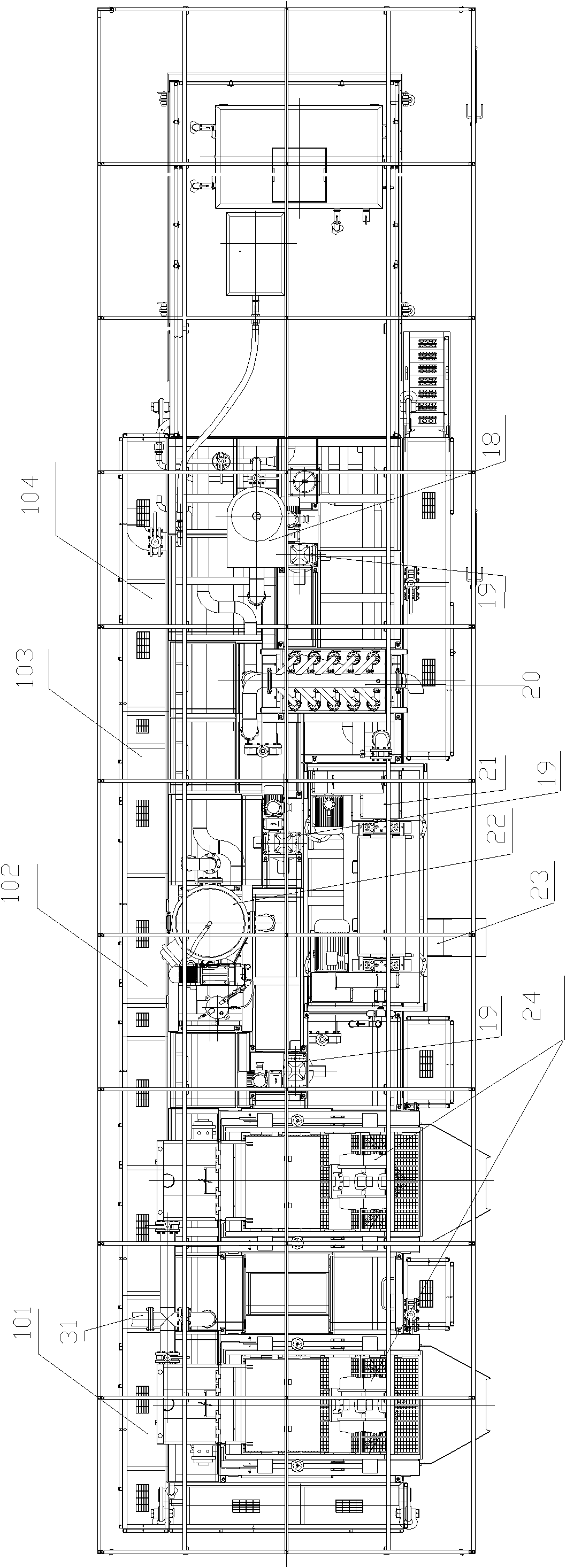
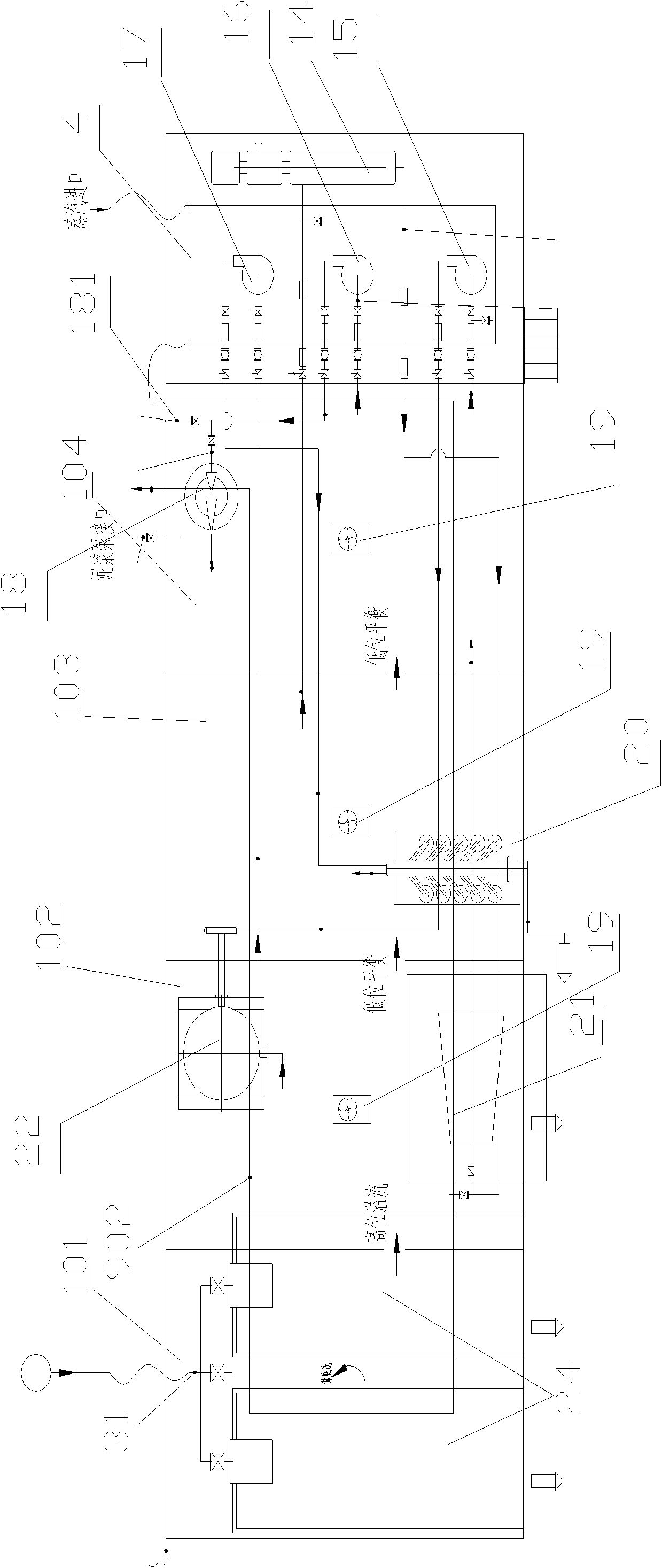
[0038] Such as figure 1 , 2As shown, a low-temperature vehicle-mounted oil drilling and workover drilling fluid purification system includes a mud tank 1, a pump skid 4, solid control equipment, equipment communication pipelines, a cleaning hot water tank, a dosing tank, and a steam heating pipeline. The solid control equipment is installed on the tank surface of the mud tank 1. The mud tank 1 is equipped with a sand cleaning port 105, and is divided into a grit chamber 101, a degassing chamber 102, a centrifuge chamber 103, and a mixing chamber 104. Arranged from left to right, each warehouse has a sequential overflow port, and each warehouse is equipped with a sand cleaning port 105. The solid control equipment includes two vibrating screens 24, a degasser 22, and a desilter device 20, a high-speed centrifuge 21, three agitators 19, a mixing funnel 18, three centr...


PUM


Abstract

The invention discloses a low-temperature vehicle-mounted oil drilling fluid purifying system during drilling and repairing, which comprises a mud tank, a pump pry, solids control equipment, an equipment communicating pipeline, a cleaning hot water tank, a feeding tank and a steam heating pipeline, wherein a sand setting bin is communicated with a degassing bin through a high-level overflow; the degassing bin is communicated with a centrifuge bin and the centrifuge bin is communicated with a mixing bin respectively low-level overflow, communicating ports of all bins are provided with valves which can be closed, a degassing device and a high-speed centrifuge are arranged on the tops of the degassing bin and the centrifuge bin, the high-speed centrifuge is close to one side of the mud tank discharging the solid phase, and the degassing device is arranged on the tank surface the mud tank with far away from one side discharging the solid phase; a mud remover is arranged at the top of the centrifuge bin and one side closes to the degassing bin and is close to the high-speed centrifuge in parallel. The invention has the advantages of integration, compact layout, convenient and rapid disassembly and assembly, rapid movement and concentrated residual removal; and in order to adapt to the cold environment, steam heating pipelines are arranged at the bottom of the mud tank, and on a water tank and the pump pry.

Description

technical field [0001] The invention relates to oil and gas exploration equipment, in particular to a low-temperature vehicle-mounted equipment for exploration, production, shallow well drilling and well workover. Background technique [0002] In oil drilling operations, drilling fluid plays the role of storage, deployment, removal of cuttings and sand particles, and control of solid phase content. It is important to ensure the safety of drilling operations and improve the efficiency of drilling and workover. ensure. Drilling fluid purification system is an important supporting device to maintain and maintain the performance of drilling fluid. Its main functions: one is to separate the impurities in the drilling fluid, such as gas, silt, cuttings, etc., to ensure the specific gravity of the drilling fluid; the other is to add ash and chemical additives to the drilling fluid to make the drilling fluid reach the ideal properties such as density and viscosity. At present, th...

Claims


Application Information

Patent Timeline
IPC IPC(8): E21B21/06
Inventor 邹晖徐凯徐杨刘挺刘丽彩
Owner CHENGDU WEST PETROLEUM EQUIP
Learn More