Self-supporting friction stir welding method with unequal diameters of upper and lower shaft shoulders and stirring head thereof

A friction stir welding technology with different diameters, applied in welding equipment, non-electric welding equipment, metal processing equipment, etc., can solve the problems of affecting joint performance, breaking of stirring needles, large welding heat input, etc., to reduce the degree of softening, prevent Fracture, reduce heat input effect

Inactive Publication Date: 2012-05-30
HARBIN INST OF TECH
View PDF0 Cites 1 Cited by
  • Summary
  • Abstract
  • Description
  • Claims
  • Application Information

AI Technical Summary

Problems solved by technology

[0003] The purpose of the present invention is to solve the problem that the upper and lower shaft shoulders are equal in diameter in the existing self-sustaining friction stir welding method, and there is a problem that the welding heat input is large and the stirring needle load is large, which affects the performance of the joint and even causes the stirring needle to break. Provide a self-sustaining friction stir welding method with different diameters of upper and lower shoulders and its stirring head

Method used


Image

  • Self-supporting friction stir welding method with unequal diameters of upper and lower shaft shoulders and stirring head thereof
  • Self-supporting friction stir welding method with unequal diameters of upper and lower shaft shoulders and stirring head thereof
  • Self-supporting friction stir welding method with unequal diameters of upper and lower shaft shoulders and stirring head thereof

Examples


specific Embodiment approach 1

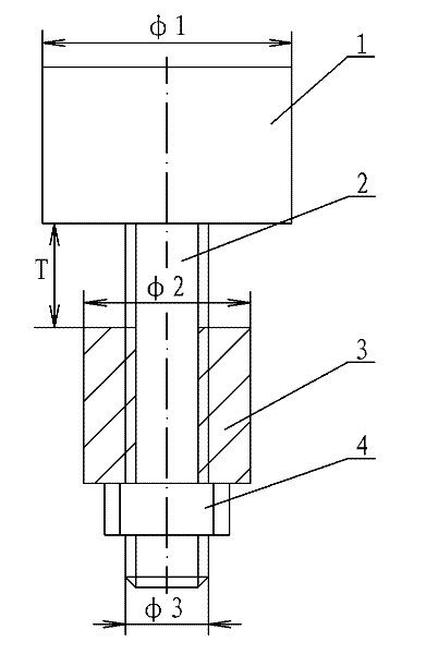
[0008] Specific implementation mode one: combine figure 2 Describe this embodiment, this embodiment is realized by the following steps: Step 1, stirring head size determination: according to the thickness of the first welded workpiece 5 and the second welded workpiece 6, determine the upper shaft shoulder diameter φ1, the lower shaft shoulder diameter φ2 and stirring needle diameter φ3: the diameter of the upper shoulder φ1 is 2.5 to 3 times the thickness t of the workpiece to be welded, the diameter of the lower shoulder φ2 is 2 to 2.5 times the thickness t of the workpiece to be welded, and the diameter of the stirring needle φ3 is the thickness of the workpiece to be welded 1.25 to 2 times of t; the size of each part of the stirring head is selected according to the thickness of the first welded workpiece 5 and the second welded workpiece 6, in order to ensure the stability of the forming of the weld seam and the quality of the joint. Step 2. Determine the use length of th...

specific Embodiment approach 2

[0009] Specific implementation mode two: combination figure 2 Describe this embodiment, the upper shaft shoulder diameter φ1 in step 1 of this embodiment is 3 times of the thickness t of the workpiece to be welded, the diameter of the lower shaft shoulder φ2 is 2 times of the thickness t of the workpiece to be welded, and the diameter of the stirring pin φ3 is the thickness of the workpiece to be welded 1.5 times the thickness t. The size of the above stirring head can ensure the stability of the weld formation. Other steps are the same as in the first embodiment.

specific Embodiment approach 3

[0010] Specific implementation mode three: combination figure 2 To describe this embodiment, in step 2 of this embodiment, the distance T between the lower end surface of the upper shoulder 1 and the upper end surface of the lower shoulder 3 is 0.3 mm smaller than the thickness t of the workpiece. The above values ​​give the best stir welding results. Other steps are the same as in the first embodiment.


PUM


Abstract

The invention relates to a self-supporting friction stir welding method with unequal diameters of upper and lower shaft shoulders and a stirring head thereof, and relates to the self-supporting friction stir welding method and the stirring head thereof. The invention aims to solve the problem that the diameters of the upper and lower shaft shoulders are equal and the problem that large heat inputof welding and bearing of a stirring pin influence the joint performance and even cause the rupture of the stirring pin in the conventional elf-supporting friction stir welding method. The method comprises the steps of: 1, determining the size of the stirring head; 2, determining the using length of the stirring pin; 3, fixing a first work piece to be welded and a second work piece to be welded; 4, positioning the stirring head; and 5, performing the stir friction welding on the first work piece to be welded and the second work piece to be welded. The stirring head and the stirring pin are vertical to the lower end face of the upper shaft shoulder; the stirring pin and the upper shaft shoulder are integrated into a whole; the outer surface of the stirring pin is provided with external threads; the lower shaft shoulder is in threaded connection with the stirring pin; a nut is arranged under the lower shaft shoulder; the nut is in threaded connection with stirring pin; and the diameter of the lower shaft shoulder is less than that of the upper shaft shoulder. The elf-supporting friction stir welding method with unequal diameters of upper and lower shaft shoulders and the stirring head thereof are used for stir friction welding.

Description

technical field [0001] The invention relates to a self-sustaining friction stir welding method and a stirring head thereof. Background technique [0002] Friction stir welding (FSW) is a new solid-phase joining technology developed by the British Welding Institute (TWI) in 1991. Compared with traditional welding methods, it has the advantages of high welding quality, low production cost and no environmental pollution. Has been successfully used in aerospace, aircraft manufacturing and railway transportation and other fields. However, conventional friction stir welding has some disadvantages, such as large welding load, heavy welding machine structure, and a backing plate of a specific shape is required during the welding process to ensure stable clamping of the workpiece. In addition, welds may have root defects that are difficult to detect. In order to solve the above problems, a self-sustaining friction stir welding method was developed. In this method, the stirring hea...

Claims


Application Information

Patent Timeline
Patent Type & Authority Patents(China)
IPC IPC(8): B23K20/12
Inventor 刘会杰赵运强侯军才张超群张会杰黄永宪于雷李金全
Owner HARBIN INST OF TECH
Why Eureka
Try Eureka