Supporting foot connecting structure and supporting foot device

A technology for connecting structures and feet, which is applied in the direction of connecting components, furniture connections, furniture parts, etc., can solve the problems of complex structure, high cost, damage to the connecting structure, etc., and achieve the effects of flexible adjustment, low cost and simple structure

Inactive Publication Date: 2011-01-12
思想人机工程有限责任公司
View PDF6 Cites 2 Cited by
  • Summary
  • Abstract
  • Description
  • Claims
  • Application Information

AI Technical Summary

Problems solved by technology

[0005] The technical problem to be solved by the present invention is to provide a support leg device and its connection structure, which can solve the problems of unstable installation of the support legs, complex structure, high cost, and easy damage of the connection structure in the existing support leg device

Method used


Image

  • Supporting foot connecting structure and supporting foot device
  • Supporting foot connecting structure and supporting foot device
  • Supporting foot connecting structure and supporting foot device

Examples


Embodiment Construction

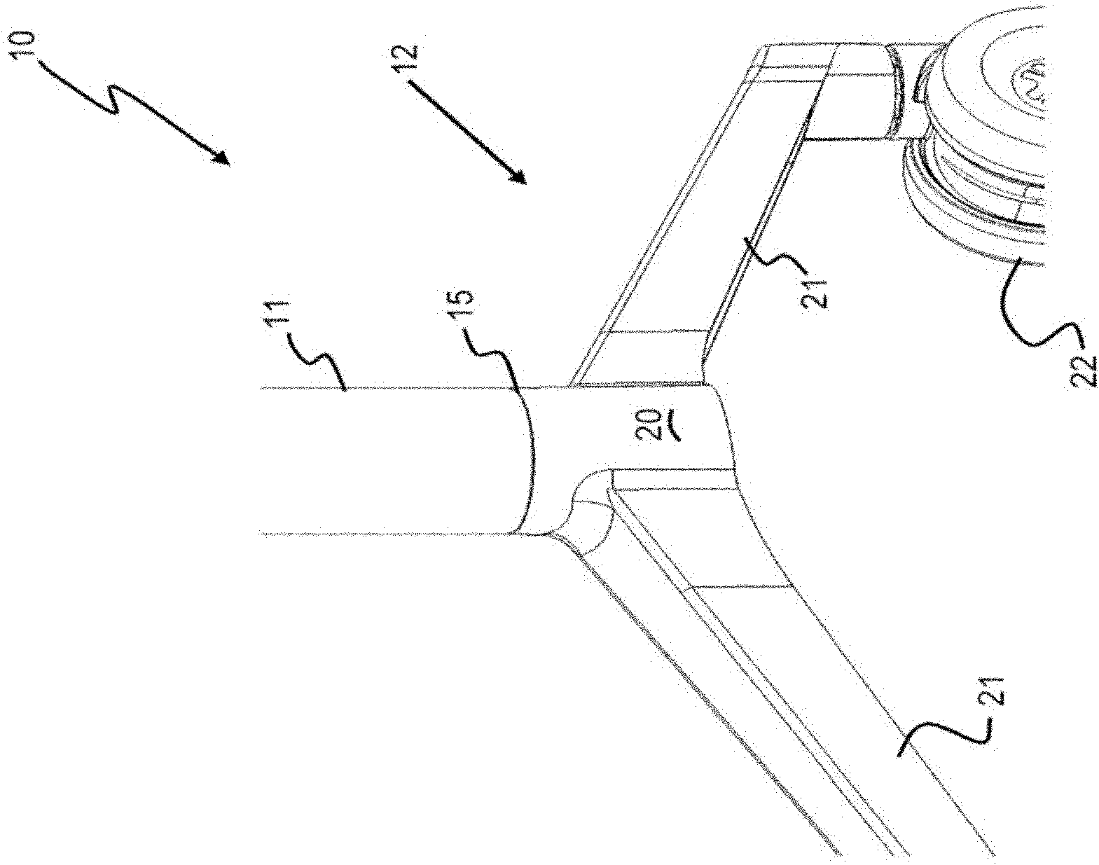
[0020] Please also refer to Figure 1-4 As shown, the leg device 10 of the present invention is a supporting structure used as furniture, such as a supporting workbench, table, dining table, writing board, reporting table, etc. The foot device 10 includes a support rod 11 , a support foot 12 , a fastener 13 and a connection structure 14 . Wherein, the supporting foot 12 is assembled on the supporting rod 11 through the connecting structure 14 , and then the supporting foot 12 is fastened to the supporting rod 11 by the fastener 13 .

[0021] The support rod 11 is preferably in a tubular structure, but is not limited to this shape, and can be designed in other shapes as required. It is hollow inside and has an inner surface 23 . The support rod 11 vertically extends upwards from the top of the support foot 12, and its top is supported under the desktop or table top (not shown), thereby supporting the table top or table top.

[0022] The support feet 12 are supported on the gr...


PUM


Abstract

The invention relates to a supporting foot device and a connecting structure thereof. The supporting foot device comprises a supporting rod, a supporting foot and a connecting structure for assembling the supporting rod and the supporting foot together. The connecting structure comprises a protruding element and a seat body which are mutually matched, wherein the protruding element comprises a plurality of protrusions; a plurality of positioning holes are correspondingly formed on the seat body; and each protrusion is fixedly supported inside a corresponding positioning hole. The supporting device has the advantages of simpler structure and lower cost. Relative motion is not generated between the supporting foot and the supporting rod, and even if a supported table moves and the supporting foot contacts other objects, the supporting foot cannot deflect relative to the supporting rod so as not to damage the connecting mechanism.

Description

technical field [0001] The invention relates to a connection structure of furniture, in particular to a furniture connection structure and a foot device using the connection structure. Background technique [0002] Connecting structures are used to connect two or more components to form a composite device. Most of the furniture or furniture involved in daily life or work needs to be supported by a supporting structure formed by assembling a plurality of supporting elements through connecting structures. For example, a table or a workbench is supported on the ground by one or more leg devices. Each foot device includes a support rod and a support foot, and the two are usually connected and fixed by a connecting structure. The upper end of the support rod is installed under the desktop or the table top. Sometimes a shaft device is installed between the support rod and the table top so that the table top is foldable relative to the support rod. [0003] The support leg stru...

Claims


Application Information

Patent Timeline
Patent Type & Authority Applications(China)
IPC IPC(8): F16B12/44A47B91/02
Inventor 克雷里奥·福特斯·德·索札马修·托马斯·克莱姆斯
Owner 思想人机工程有限责任公司
Why Eureka
Try Eureka