
Method of driving touch panel, capacitance-type touch panel, and display apparatus

一种触控面板、驱动控制电路的技术,应用在驱动检测触控的触控面板,触控面板和具有触控检测功能的显示装置领域,能够解决不能触控信号区分开等问题

Active Publication Date: 2011-01-05
JAPAN DISPLAY INC
View PDF5 Cites 32 Cited by
  • Summary
  • Abstract
  • Description
  • Claims
  • Application Information

AI Technical Summary

Problems solved by technology

Interference noise is therefore hardly distinguishable from touch signals that would be normally detected in a frequency band equal to or lower than the Nyquist frequency

Method used


Image

  • Method of driving touch panel, capacitance-type touch panel, and display apparatus
  • Method of driving touch panel, capacitance-type touch panel, and display apparatus
  • Method of driving touch panel, capacitance-type touch panel, and display apparatus

Examples


no. 2 example

[0047] 4. Application examples

[0048] 5. Other variants

[0049] 1. The principle of capacitive touch detection

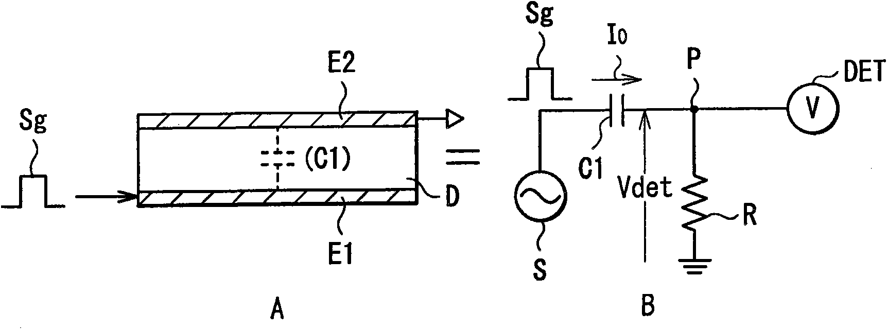
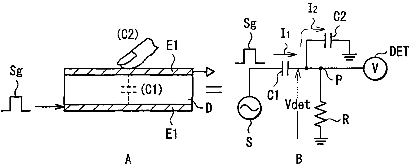
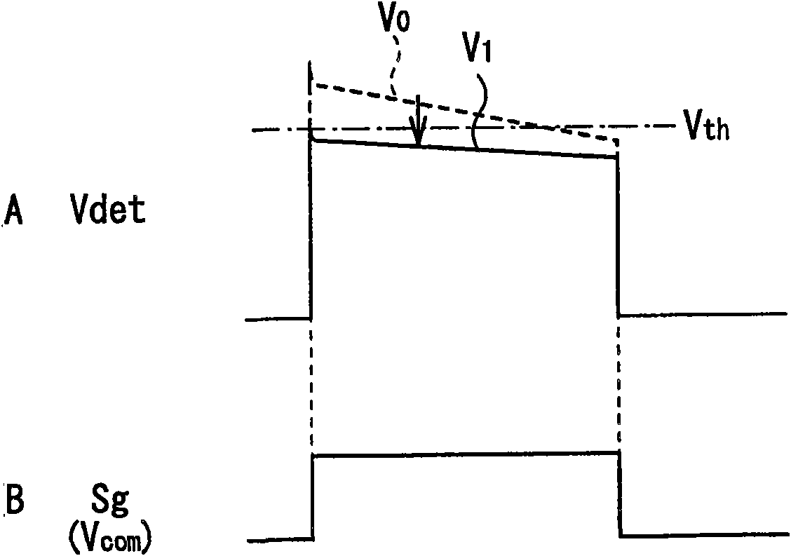
[0050] First, refer to figure 1 A and figure 1 B to image 3 The principle of the touch detection method for each of the touch panel and the display device with touch detection function according to the embodiments of the present invention will be described. The touch detection method is embodied as a capacitive touch sensor, in which a pair of electrodes (a drive electrode E1 and a detection electrode E2) arranged oppositely are used to configure a capacitive element, and a dielectric D is located between the pair of electrodes, for example, as figure 1 As shown in A. Such a structure is expressed as figure 1 Equivalent circuit shown in B. The drive electrode E1 , the detection electrode E2 and the dielectric D collectively configure the capacitive element C1 . One end of the capacitive element C1 is connected to an AC signal source (drive signal source)...

application example 1

[0159] Figure 19 The appearance of a television device using a display device or the like having a touch detection function according to each embodiment is shown. The television device has, for example, a front panel 511 and a video display screen 510 including a filter glass 512 configured by a display device or the like having a touch detection function according to each embodiment.

application example 2

[0161] Figure 20A with Figure 20B The appearance of a digital camera using a display device or the like having a touch detection function according to each embodiment is shown. The digital camera has, for example, a light emitting portion 521 for flash, a display 522 , a menu switch 523 , and a shutter button 524 , and the display 522 is configured by a display device or the like having a touch detection function according to each embodiment.


PUM


Abstract

A capacitance-type touch panel, allowing disturbance noise and touch detection time to be reduced and having a simple configuration, is provided. The capacitance-type touch panel including: a plurality of drive electrodes each having a strip shape; a drive control circuit performing control such that a drive signal for touch detection is selectively applied to the drive electrodes; a plurality of touch detection electrodes arranged to intersect with the drive electrodes in such a manner that capacitance is formed in each intersecting part, and each outputting a detection signal in synchronization with the drive signal; and a detection circuit detecting an external proximity object based on the detection signal. The drive control circuit controls application of the drive signal in such a manner that the detection signal is a polarity-alternating signal including a positive-negative asymmetrical signal component which is due to presence of the external proximity object.

Description

technical field [0001] The present invention relates to a touch panel that can input information by the user touching or approaching with a finger, etc., and more particularly to a method for driving and detecting a touch panel based on a change in capacitance, and using the method A touch panel and a display device with a touch detection function. Background technique [0002] Recently, a display device is attracting attention, in which a contact detector (so-called touch panel) is mounted on a display device such as a liquid crystal display device, and various button images are displayed on the display device in order to allow Information input for the alternative to the button. Although there are several types of touch panels including optical type and resistive type, mobile terminals especially expect capacitive type touch panels due to their relatively simple structure and low power consumption. However, in the case of a capacitive touch panel, the human body acts as ...

Claims


Application Information

Patent Timeline
Patent Type & Authority Applications(China)
IPC IPC(8): G06F3/044G02F1/133
CPCG06F3/044G02F1/13338G06F3/0446
Inventor 野口幸治原田勉木田芳利中西贵之石崎刚司竹内刚也
Owner JAPAN DISPLAY INC
Learn More