Waterproof coding device

A coding device and knob technology, which is applied in the field of coding devices, can solve the problems of high cost and achieve the effects of low cost, convenient assembly and safe use

Inactive Publication Date: 2012-06-13
SHENZHEN CHK
View PDF0 Cites 1 Cited by
  • Summary
  • Abstract
  • Description
  • Claims
  • Application Information

AI Technical Summary

Problems solved by technology

[0005] Electromagnetic induction type: the switch is realized by the iron core and the inductance coil, and the cost is high

Method used


Image

  • Waterproof coding device
  • Waterproof coding device
  • Waterproof coding device

Examples


Embodiment Construction

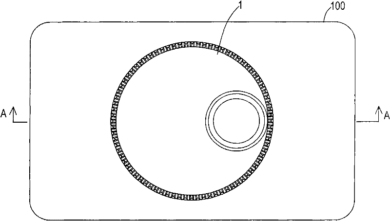
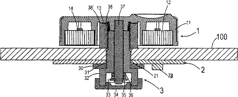
[0021] refer to Figure 1-2 , The waterproof coding device includes: a knob 1, an induction switch plate 2 and an installation and positioning component 3.

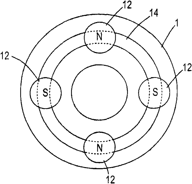
[0022] The knob 1 includes a cover 11 and a plurality of magnets 12 fixed in the cover 11 and arranged in a ring shape.

[0023] The inductive switch board 2 is located at the lower side of the knob 1, and an installation hole 21 and two Hall elements 23, 23' (23' are arranged on the inductive switch board 2 figure 1 , 2 not shown in ), the positions of the two Hall elements 23, 23' should be such that after the knob 1 rotates 360 degrees, all the magnets 12 of the knob 1 pass above the two Hall elements 23, 23', in other words , when the knob 1 is turned, the magnetic fields of all the magnets 12 of the knob 1 have a chance to penetrate the two Hall elements 23, 23'. In this way, when the knob 1 is turned, the two Hall elements 23, 23' can output pulse coded signals representing the angular displacement of the knob 1....


PUM


Abstract

A waterproof coding device comprises a knob, an inductive switch board and an installing and locating assembly, wherein the knob comprises a cover body and a plurality of circularly arranged magnets fixedly arranged in the cover body; the inductive switch board is positioned below the knob; the inductive switch board is provided with an installing hole and two Hall elements; the installing and locating assembly comprises shaft sleeves with locating convex plates at one end and a shaft; the shaft sleeves are connected with a lock sleeve after running through the installing hole of the inductive switch board and an enclosure; the locating convex plates of the shaft sleeves are provided with an assembling cavity inside; a waterproof cover is installed at the entrance of the assembling cavity; and one end of the shaft is fixedly connected with the knob and the other end thereof is positioned in the assembling cavity of the shaft sleeves and is provided with clamp rings. The coding device has simple structure and low cost and is convenient to process and assemble. Besides, the coding device can safely and stably work in the humid environment or the environment in which water is sprayed. The coding device is further provided with a knob locating mechanism, thus ensuring the knob not to turn with low amplitude when being vibrated.

Description

technical field [0001] The invention relates to an encoding device, in particular to a waterproof encoding device for converting angular displacement into encoded digitized electrical signals. Background technique [0002] The encoding device is a sensor device that converts angular displacement or linear displacement signals into encoded digital electrical signals. The former is called a code disc, and the latter is called a yardstick. According to the reading method, the encoding device can be divided into two types: contact type and non-contact type. The contact type adopts the brush output, and the state of the code is "1" or "0" when the brush touches the conductive area or the insulating area; the non-contact type accepts the sensitive element is a photosensitive element or a magnetic sensitive element, and when the photosensitive element is used, the code is "1" or "0". The light-transmitting area and the opaque area indicate whether the state of the code is "1" or ...

Claims


Application Information

Patent Timeline
Patent Type & Authority Patents(China)
IPC IPC(8): G01D5/249
Inventor 丘守庆许申生马艳明
Owner SHENZHEN CHK
Why Eureka
Try Eureka