Method for slotting anode
An anode and mold core technology, applied in the field of aluminum electrolysis, achieves the effects of high efficiency, small footprint, and reduced electrolysis energy consumption
- Summary
- Abstract
- Description
- Claims
- Application Information
AI Technical Summary
Problems solved by technology
Method used
Image
Examples
specific Embodiment approach
[0038] The following will clearly and completely describe the technical solutions in the embodiments of the present invention with reference to the accompanying drawings in the embodiments of the present invention. Obviously, the described embodiments are only some, not all, embodiments of the present invention. Based on the embodiments of the present invention, all other embodiments obtained by persons of ordinary skill in the art without creative efforts fall within the protection scope of the present invention.
[0039] In the embodiment of the present invention, by using the driving device to extract the mold core plate from both sides of the mold casing, not only can the groove in the middle top be lower than the tops at both ends, but also the process is simple, the use is convenient, and the space occupied is small.
[0040] The following are specific examples.
Embodiment 1
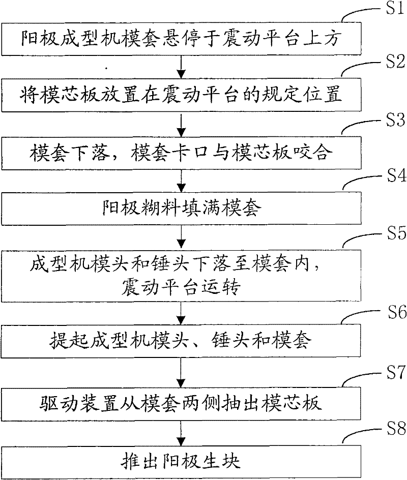
[0041] Embodiment one, see figure 1 , is the flow chart of this embodiment.
[0042] Step S1, the die set of the anode forming machine hovers above the vibrating platform.
[0043] Step S2, placing the mold core plate on the specified position of the vibrating platform.
[0044] When placing the core plate, auxiliary tools can be used to fix it, for example, the position can be marked on the vibration platform, or the driving device can be set in advance, and the core plate can be controlled by the driving device.
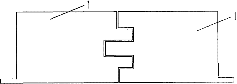
[0045] see figure 2 , The core plate 1 is composed of two left and right pieces to facilitate the extraction of the core plate after the anode green block is formed. The left and right mold core panels are airtight and seamless to ensure the strength of the mold core panels; the left and right parts can be connected by a fixing device, or fixed to each other by shape fit. figure 2 What is shown in is only an example, and the joints of the left and right core...
Embodiment 2
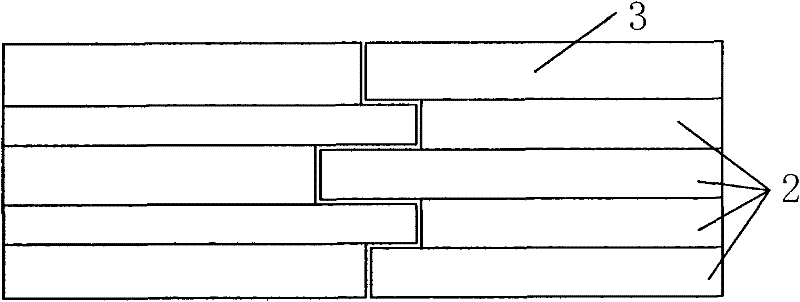
[0072] The steps are roughly the same as the above-mentioned first embodiment, the difference is that the mold core plate is composed of upper and lower parts.
[0073] The upper and lower parts of the core plate are airtight and seamless to ensure the strength of the core plate; it can be connected by a fixing device, which can be a structure similar to a C-type pin, and the two ends of the C-type pin are respectively inserted into the core plate upper and lower parts. Alternatively, the joint between the upper and lower parts of the mold core plate is a shape that facilitates the extraction of the lower half of the mold core plate.
[0074] see Figure 9 and Figure 10 , when pulling out the core plate from the anode green block, first pull out the lower part of the core plate (that is, the covering strip 2) from one side of the mold casing, and let the upper part of the core plate (that is, the first covering strip 3) fall naturally into the position of the original lowe...
PUM
 Abstract
Description
Claims
Application Information
 - R&D
- Intellectual Property
- Life Sciences
- Materials
- Tech Scout
- Unparalleled Data Quality
- Higher Quality Content
- 60% Fewer Hallucinations
Browse by: Latest US Patents, China's latest patents, Technical Efficacy Thesaurus, Application Domain, Technology Topic, Popular Technical Reports.
© 2025 PatSnap. All rights reserved.Legal|Privacy policy|Modern Slavery Act Transparency Statement|Sitemap|About US| Contact US: help@patsnap.com


