
Automatic burning temperature control system

A temperature control system and automatic technology, applied in the control of combustion, lighting and heating equipment, etc., can solve problems such as over-temperature, low temperature, regional temperature channeling, and inability to achieve process effects, achieve no temperature fluctuations, and increase equipment utilization. , the effect of less heat loss

Inactive Publication Date: 2010-12-15
苏州工业园区姑苏科技有限公司
View PDF0 Cites 6 Cited by
  • Summary
  • Abstract
  • Description
  • Claims
  • Application Information

AI Technical Summary

Problems solved by technology

[0002] The combustion control system has been applied in heat treatment. In the existing technology, the gas heating control system of heat treatment equipment is generally composed of ordinary intermediate relays, contactors, temperature control meters, etc., and often occurs during the temperature control process. High temperature, low temperature, and temperature shifting between regions lead to many process defects in the workpiece during the heat treatment process, and the ideal process effect cannot be achieved.

Method used


Image

  • Automatic burning temperature control system
  • Automatic burning temperature control system

Examples


Embodiment Construction

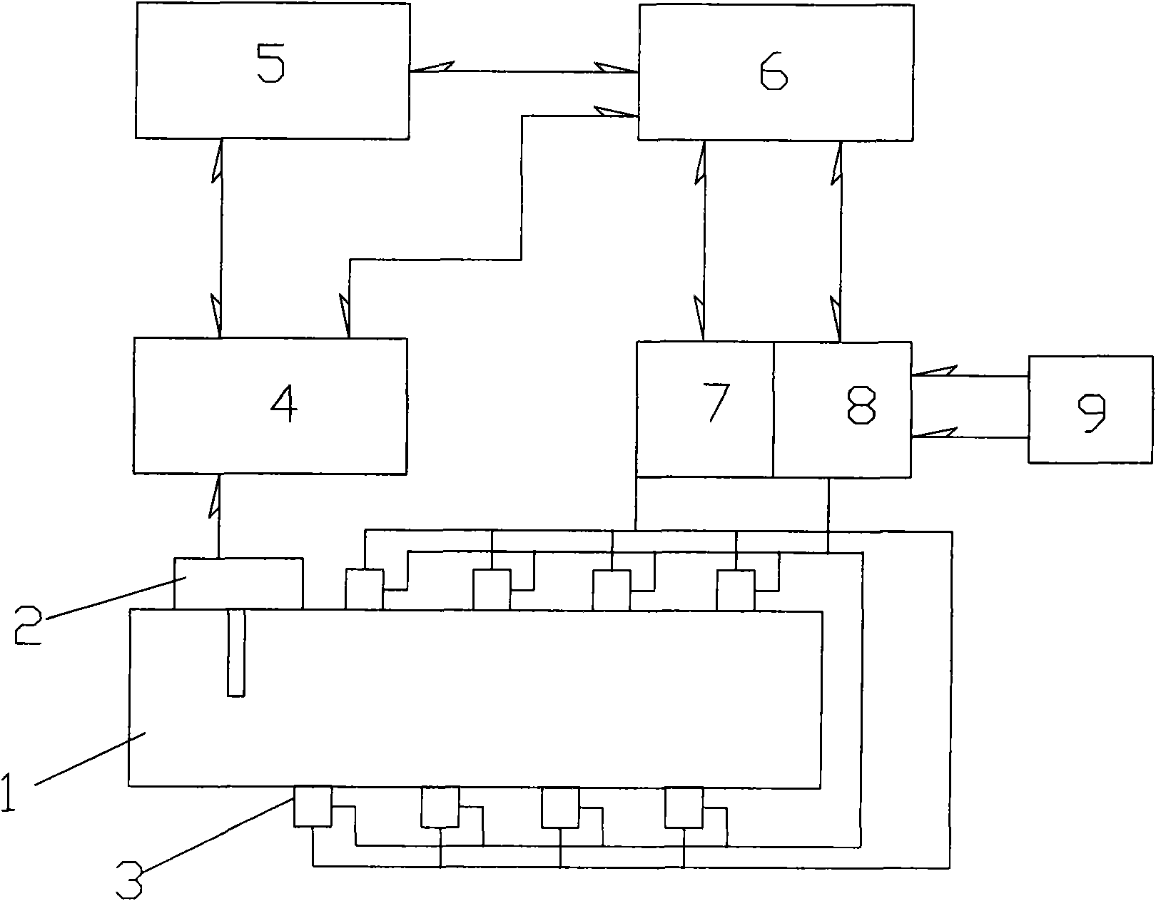
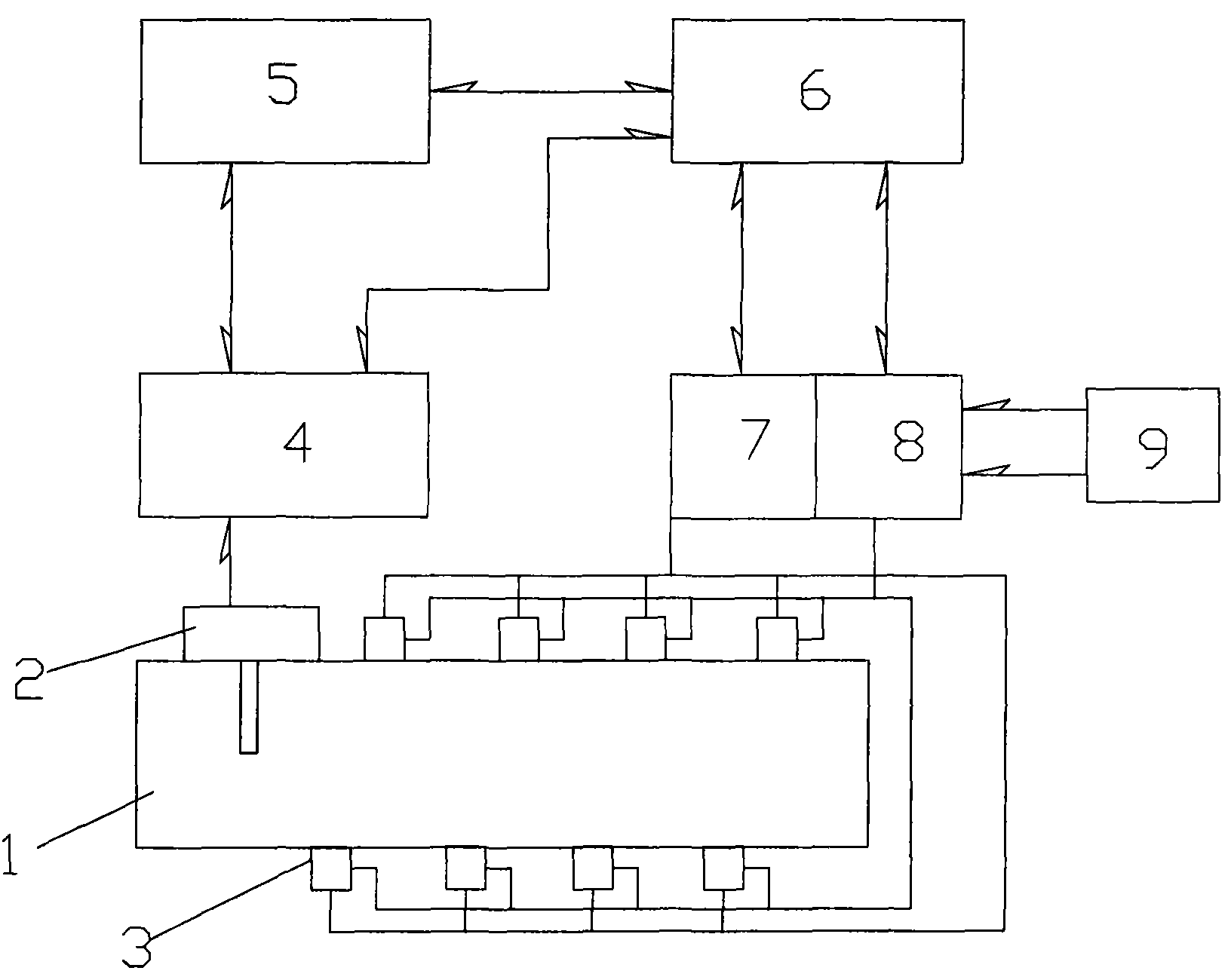
[0009] A kind of burning automatic temperature control system as shown in the accompanying drawing, it comprises furnace 1, described furnace 1 is provided with thermocouple 2 and burner 3 described thermocouple 2 is connected with temperature instrument 4, and described temperature instrument 4 is connected with respectively The upper computer 5 is connected with the programmable controller 6, and the programmable controller 6 is connected with the upper computer 5, the proportional valve 7 and the electromagnetic valve 8 respectively, and the proportional valve 7, the electromagnetic valve 8 are connected with the burner 3, and the Solenoid valve 8 links to each other with air gas tank 9.

[0010] The principle is: the combustion temperature control is collected by the thermocouple 2 and the temperature signal inside the furnace 1 is transmitted to the temperature instrument 4, and the temperature instrument 4 then transmits the control signal (PID) to the programmable contro...


PUM


Abstract

The invention relates to an automatic burning temperature control system, which comprises a furnace, wherein the furnace is provided with a thermocouple and a burner; the thermocouple is connected with a temperature instrument which is respectively connected with an upper computer and a programmable controller; the programmable controller is respectively connected with the upper computer, a proportional valve and a solenoid valve; the proportional valve and the solenoid valve are connected with the burner; and the solenoid valve is connected with an air / gas tank. The automatic burning temperature control system realizes intelligent control, can rapidly raise the temperature of the furnace without temperature fluctuation, and has the advantages of increase of equipment utilization ratio, low heat loss, energy saving and low manufacturing cost.

Description

Technical field: [0001] The invention relates to an automatic temperature control system for combustion. Background technique: [0002] The combustion control system has been applied in heat treatment. In the existing technology, the gas heating control system of heat treatment equipment is generally composed of ordinary intermediate relays, contactors, temperature control meters, etc., and often occurs during the temperature control process. High temperature, low temperature, and temperature shifting between regions lead to many process defects during the heat treatment process of the workpiece, and the ideal process effect cannot be achieved. Invention content: [0003] In order to solve the above-mentioned technical problems, the present invention provides a brand-new combustion automatic temperature control system that realizes constant temperature. [0004] The technical solution adopted by the present invention to solve the technical problem is: a combustion automat...

Claims


Application Information

Patent Timeline
Patent Type & Authority Applications(China)
IPC IPC(8): F23N5/00
Inventor 张成勇
Owner 苏州工业园区姑苏科技有限公司
Learn More