
Fixing seat of elevator guide rail

A technology for elevator guide rails and fixed seats, which is used in elevators, transportation and packaging, etc., can solve problems such as inability to guarantee parallelism, force deflection of guide rails, loud noise, etc., so as to save the complicated process of gaskets and ensure smooth operation of bridge boxes. , to ensure the effect of installation accuracy

Inactive Publication Date: 2010-12-15
郭自刚
View PDF4 Cites 2 Cited by
  • Summary
  • Abstract
  • Description
  • Claims
  • Application Information

AI Technical Summary

Problems solved by technology

However, the thickness of the gasket is between 0.5 and 0.8mm. If the installation error is below 0.5mm, it will not be possible to fine-tune the installation for accurate positioning. Moreover, this gasket installation method is complicated to operate, and it is often repeated many times before it is basically in place.
[0004] At the same time, the parallelism between the outer plate of the fixed seat and the bottom plate is randomly welded, which cannot guarantee the parallelism of the two, and the two fixed installation methods of fixing the bottom plate on the wall of the hoistway cannot guarantee the outer surface of the outer plate of the fixed seat and the transverse plate of the guide rail. Therefore, when the outer surface of the transverse plate of the guide rail and the outer surface of the outer plate of the fixed seat are fitted and fixed, the flatness of the two cannot achieve a full plane fit. There is only a single line of pressing or a few points of pressing. full surface contact
Inserting gaskets between the two also cannot guarantee the flatness. If the flatness cannot be maintained, the guide rail will produce a slight deflection when it is stressed.

Method used


Image

  • Fixing seat of elevator guide rail
  • Fixing seat of elevator guide rail

Examples


Embodiment Construction

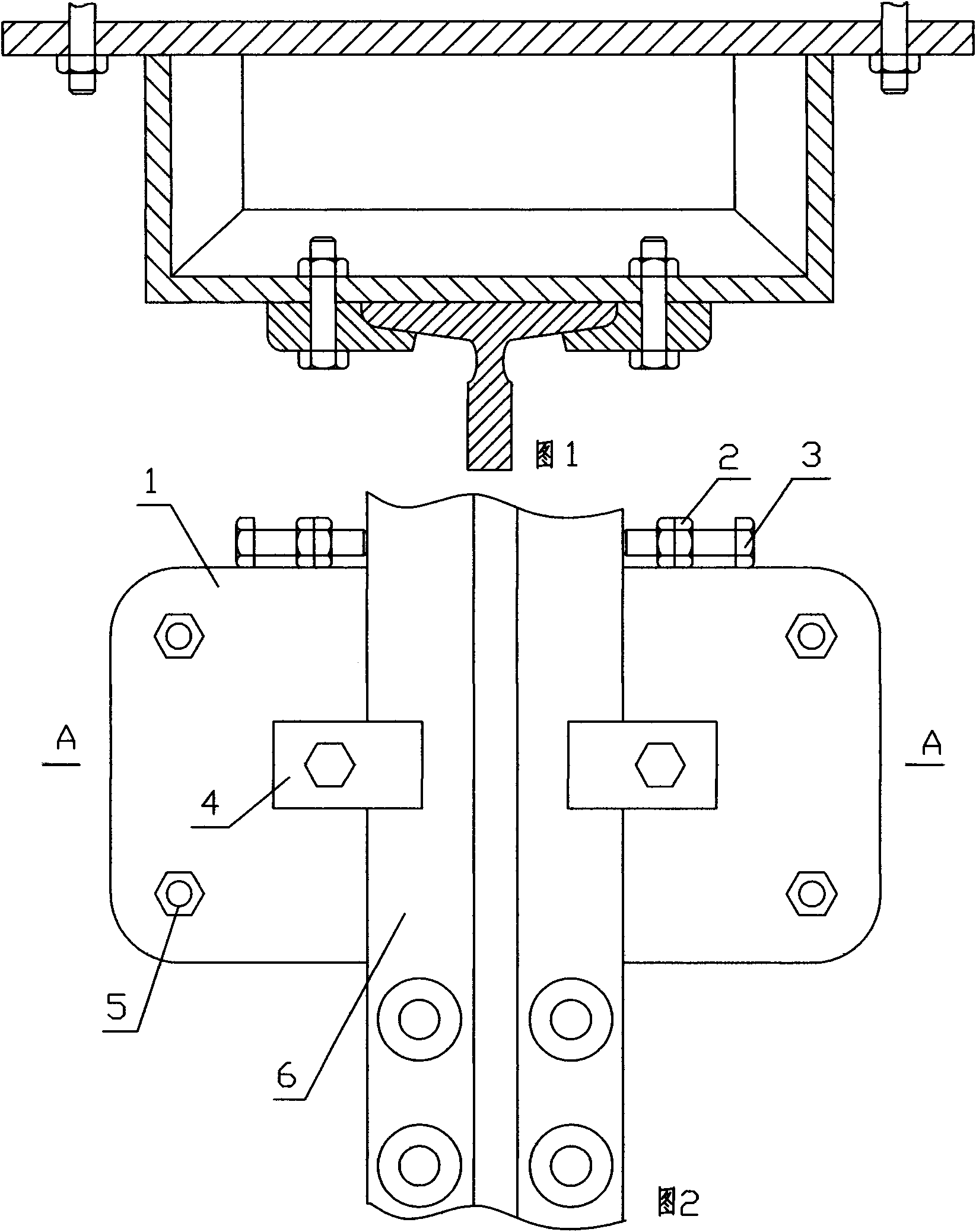
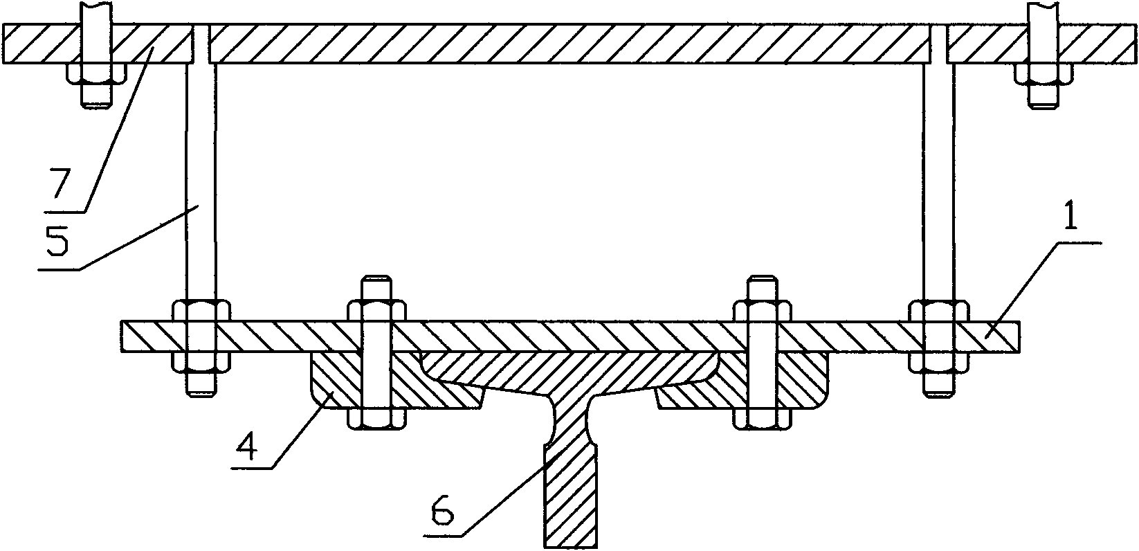
[0011] The structure of the present invention consists of a bottom plate 7, a "door"-shaped bracket, and a pressure plate 4, and is characterized in that: the "door"-shaped bracket is composed of four pins 5 vertically welded to the four corners of the bottom plate 7, a rectangular outer plate 1, and eight nuts , each pin column 5 outer parts are machined with external threads, and the outer plate 1 is evenly distributed with through holes corresponding to the four pin columns 5, after the four pin columns 5 respectively pass through the four through holes of the outer plate 1, each Two nuts are used to fix the outer plate 1 on both sides of the outer plate 1 on the external thread of the outer part of the root pin 5, and the middle part of the outer plate 1 is provided with two fixing holes for the pressure plate 4, and two fixing bolts and nuts are used to fix the two pressure plates. 4 are respectively fixed on the outer plate 1.

[0012] The four corners of the bottom are ...


PUM


Abstract

The invention discloses a fixing seat of an elevator guide rail and relates to the fixing devices of elevator guide rails. The fixing seat consists of a base plate, a gate-shaped bracket and pressing plates. The fixing seat is characterized in that: the gate-shaped bracket consists of four pins vertically welded at four corners of the base plate, a rectangular outer side plate and eight nuts, wherein outer screw threads are processed on the outer side part of each pin; through holes corresponding to the four pins are uniformly distributed on the outer side plate; after the four pins respectively run through the four through holes of the outer side plate, the outer side plate is fixed by two nuts on two side faces of the outer side plate on the outer screw threads on the outer side part of each pin; two fixing holes for the pressing plates are formed on the middle part of the outer side plate; and additionally, two fixing bolt nuts respectively fix two pressing plates on the outer side plate. The fixing seat of the elevator guide rail has the advantages that: the planeness and the fitness between the outer side plate and a transverse plate of the guide rail can be freely adjusted by adjusting each pair of nuts on the four pins; the operation is simplified; complex process of gasket is eliminated; fine turning can be actualized; the installation accuracy is ensured; and the running of an elevator car is more stable.

Description

Technical field: [0001] The invention relates to an elevator guide rail fixing device. Background technique: [0002] When the elevator is running, the power transmission mechanism above the shaft drives the axle box to move up and down through the pulley block. In order to run the axle box smoothly up and down, U-shaped guide shoes are fixed on both sides of the axle box, respectively, and the "D"-shaped vertical rails fixed on the wall of the hoistway are respectively fixed. Make a limit slide on the guide rail and run up and down. And " T " font guide rail is installed and fixed on the several guide rail holders that are evenly spaced up and down on the shaft wall. [0003] The existing guide rail fixing seat consists of a base plate, a "door"-shaped support welded on the base plate, and a pressing plate. There are two or four through holes on the bottom plate, which are fixed on the well wall by expansion bolts, or the bottom plate and the iron plate pre-buried on the ...

Claims


Application Information

Patent Timeline
Patent Type & Authority Applications(China)
IPC IPC(8): B66B7/02
Inventor 郭自刚
Owner 郭自刚
Learn More