Straight-line piston fluid engine with wobble drive valve actuation

A technology of oscillating drive and piston, applied in the field of axial piston fluid engine, can solve the problems of high production cost, maintenance and lubrication of the engine

Inactive Publication Date: 2010-12-08
罗伯特·格林
View PDF6 Cites 8 Cited by
  • Summary
  • Abstract
  • Description
  • Claims
  • Application Information

AI Technical Summary

Problems solved by technology

Commercial development of this type of engine has not been undertaken, possibly due to relatively high production costs and maintenance and lubrication issues
Scaling of large and small engines can also be an issue due to restricted space for valve piping and actuation

Method used


Image

  • Straight-line piston fluid engine with wobble drive valve actuation
  • Straight-line piston fluid engine with wobble drive valve actuation
  • Straight-line piston fluid engine with wobble drive valve actuation

Examples


Embodiment Construction

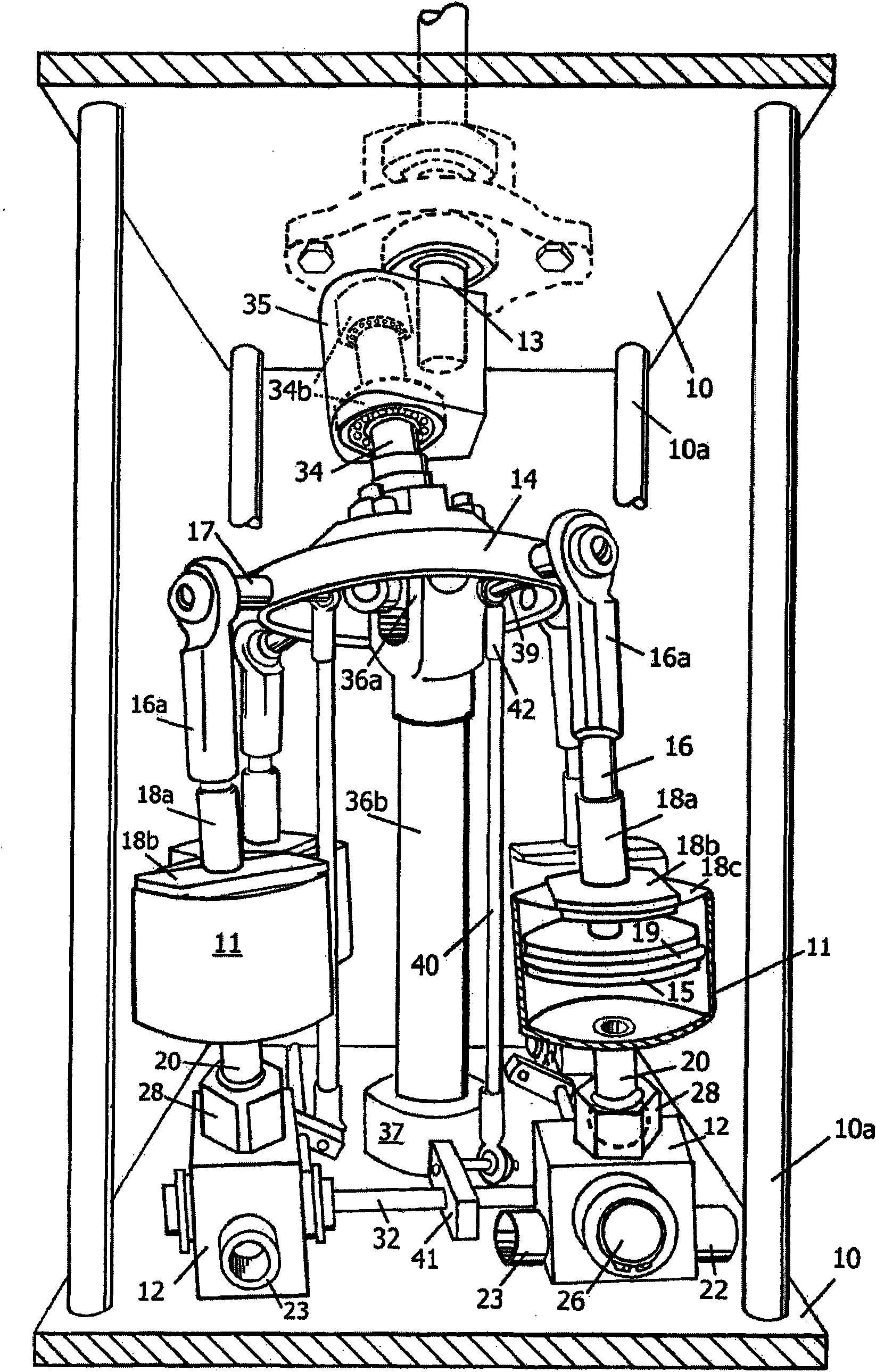
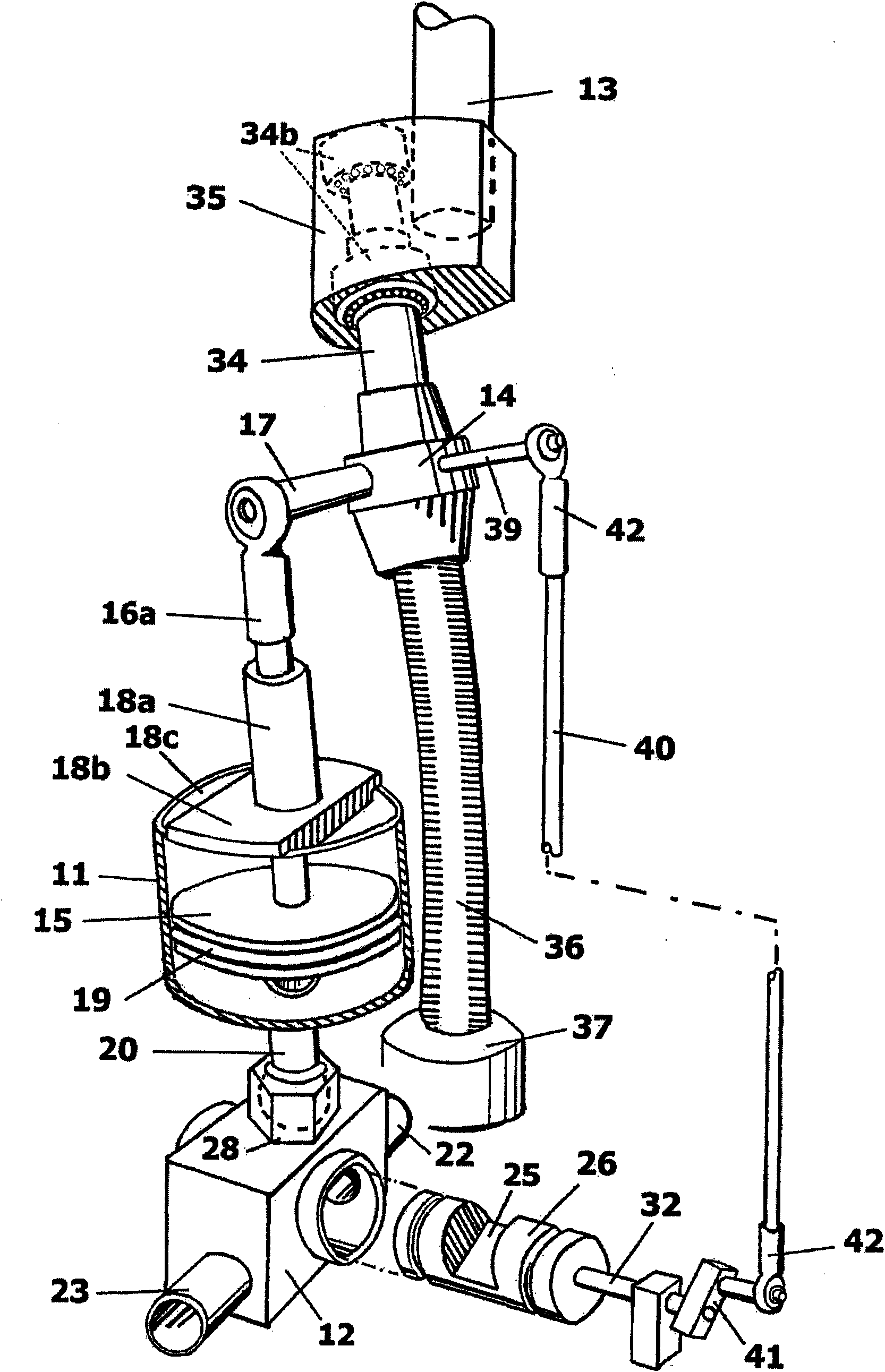
[0015] Refer to the diagram for details, figure 1 As a preferred embodiment there is shown an axial piston engine having a frame assembly with four legs 10a connecting two end walls generally indicated by the numeral 10 which operate in appropriate The relationship supports four basic components consisting of four identical articulated cylinder assemblies 11 pivotally connected to a fixed steam delivery valve assembly 12, an output crankshaft 13, an oscillating drive member 14 which drives Components interconnect the cylinder assemblies with the crankshaft.

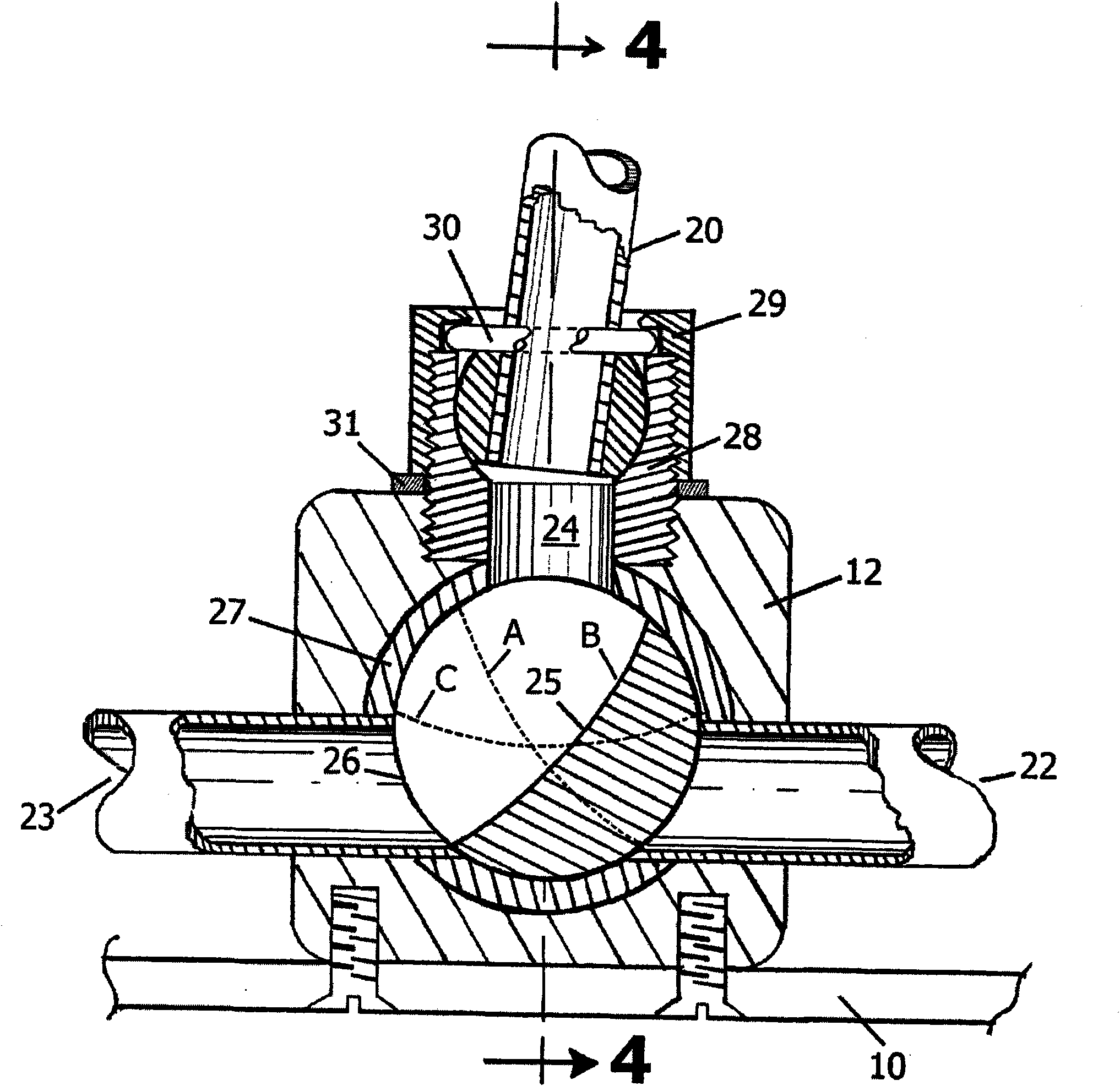
[0016] shown in figure 1 with figure 2 The cylinder assembly 11 in consists of a cylinder pivoted to the valve assembly 12 by a ball swivel sleeve joint 20 . Tube 20 is secured to the bottom of the cylinder, contains a hollow ball of durable metal or ceramic material and is pivotally mounted within an equally durable rotating sleeve joint 28 which is replaceably connected to valve 12. A piston disc 15 within the cyl...


PUM


Abstract

An axial piston fluid engine having single-acting cylinders 11 incorporating swivel-joint attachment 28 of the cylinders to rotary control valves 12 wherein straight-line piston movement is established for the elimination of side forces on the pistons 15. The pistons 15 and the control valves 12 are operatively connected to a common wobble drive member 14 and arranged in geometry of lever positions to coactively time the drive fluid into and out of the cylinders intermittently.

Description

technical field [0001] The invention relates to an axial piston fluid engine with single-acting cylinders pivotally attached to rotary valves actuated by oscillating drive members. Background technique [0002] Axial piston steam engine types are known in the art having a plurality of pistons pivotally run along parallel axes by a wobble plate mechanism. See for example US Patent 4,491,057 (Ziegler, 1985). As in other examples in US Patent 4,106,354 (Girodin, 1978), these engines are housed within a rigid block and have fixed and stationary cylinders. These pistons have ball-joint piston rods that push and pull against a wobble plate mechanism to convert piston motion into rotary motion. [0003] The engines in these examples have many precision machined parts and castings as well as engine blocks for jacketing. These engines are relatively heavy for the power they are capable of producing. These pistons are subject to side pressure from angular piston rod adjustment. A...

Claims


Application Information

Patent Timeline
Patent Type & Authority Applications(China)
IPC IPC(8): F01B3/00
CPCF01B3/0094F01B3/0002Y10T74/18336
Inventor 罗伯特·格林
Owner 罗伯特·格林
Why Eureka
Try Eureka