
Liquid-crystal handwriting screen and method for improving linearity of ambient antenna thereof

A liquid crystal handwriting and liquid crystal screen technology, which is applied to antennas, antenna arrays, antenna supports/mounting devices, etc., can solve problems such as loss of smooth function, enlarged antenna size, and abnormal linear function of handwriting functions, so as to improve antenna linearity Effect

Inactive Publication Date: 2010-12-01
UC LOGIC TECH CORP
View PDF2 Cites 16 Cited by
  • Summary
  • Abstract
  • Description
  • Claims
  • Application Information

AI Technical Summary

Problems solved by technology

In this design, the antenna plate for handwriting input is embedded in the middle of the LCD module. When the front stylus is in use, it is limited by the iron frame on the front of the LCD module around the LCD module, so that the electronic magnetic field signal of the stylus cannot be compared with ordinary handwriting. There are more than three antennas on the top, bottom, or left and right sides of the board or the middle area of ​​the handwriting screen to compare the signal strength, and the signal received by the stylus that forms the sensing area of ​​the top, bottom, left, and right antennas is due to the iron around the front of the LCD module. Due to the frame limitation and the size limitation of the LCD module, it is impossible to increase the size of the antenna in the LCD module and add the top, bottom, left and right antennas.
Under the above-mentioned limitations, the handwriting screen formed by adding an LCD screen and an electromagnetic handwriting board antenna cannot perform the handwriting function in the top, bottom, left, and right antenna areas, and will lose the smooth function, that is, the so-called linearity of the handwriting function. malfunction

Method used


Image

  • Liquid-crystal handwriting screen and method for improving linearity of ambient antenna thereof
  • Liquid-crystal handwriting screen and method for improving linearity of ambient antenna thereof
  • Liquid-crystal handwriting screen and method for improving linearity of ambient antenna thereof

Examples


Embodiment Construction

[0031] In order to further illustrate the technical means adopted by the present invention and its effects, the following describes in detail in conjunction with preferred embodiments of the present invention and accompanying drawings.

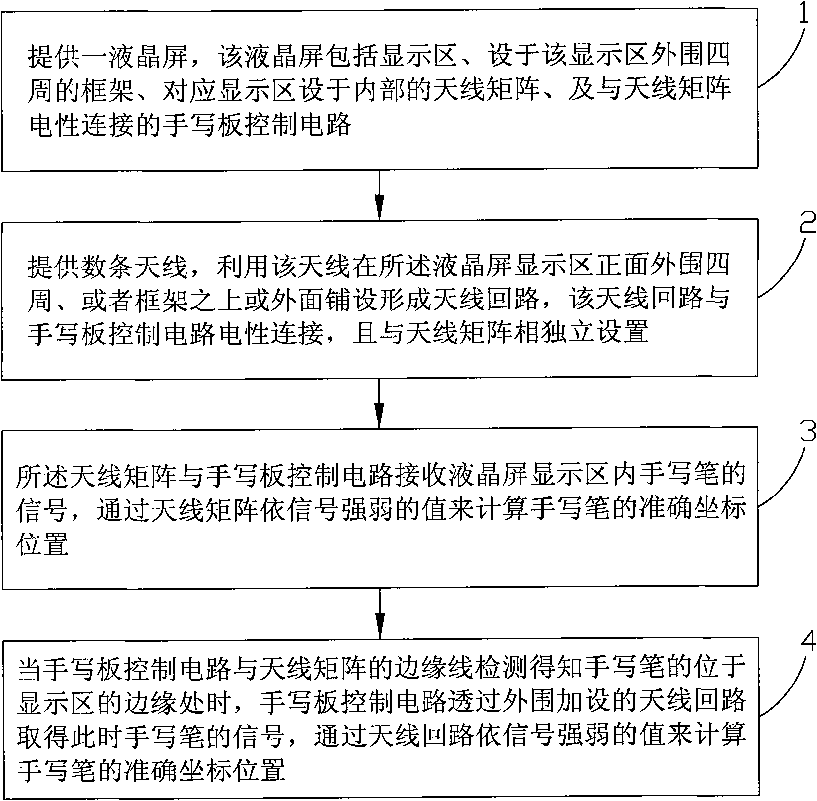
[0032] Such as figure 1 As shown, the present invention provides a kind of method for improving antenna linearity around the liquid crystal handwriting screen, and it comprises the steps:

[0033] Step 1. Provide a liquid crystal screen. The liquid crystal screen includes a display area, a frame arranged around the periphery of the display area, an antenna matrix arranged inside corresponding to the display area, and a tablet control circuit electrically connected to the antenna matrix. As a specific embodiment of the present invention, the liquid crystal screen includes a display area located in the middle of the front, a frame arranged around the periphery of the display area, a backlight module, an antenna plate, and a back iron arranged su...


PUM


Abstract

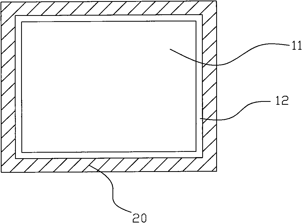
The invention relates to a liquid-crystal handwriting screen and a method for improving linearity of an ambient antenna thereof. The liquid-crystal handwriting screen comprises a liquid-crystal screen and an antenna loop, wherein the liquid-crystal screen comprises a display zone, a frame, an antenna array and a handwriting control circuit, wherein the frame is arranged around the periphery of the display zone, the antenna array is correspondingly arranged in the display zone, and the handwriting control circuit is electrically connected with the antenna array; and the antenna loop is laid around the periphery of the front surface of the display zone or above or outside the frame, s electrically connected with the handwriting control circuit and is independent from the antenna array. As the antenna loop is laid around the front surface of the liquid-crystal screen and is placed outside the display zone on the front surface of the LCD liquid-crystal screen or above or outside the frame, the antenna is not limited by an LCD iron member or the frame, and the antenna loop is arranged on a single loop frame so that the handwriting screen can be improved in middle zones or under the conditions of limitation, separation and interference.

Description

technical field [0001] The invention relates to a liquid crystal handwriting screen, in particular to a method for improving the antenna linearity around the liquid crystal handwriting screen and the structure of the liquid crystal handwriting screen. Background technique [0002] The general electromagnetic tablet is emitted (generated) by the stylus with a specific or variable frequency magnetic field generated by the button press area. The absolute position of the stylus in the antenna matrix circuit can be obtained through a specific antenna circuit design, and then through the electronic circuit, The software design enables the movement and position change of the stylus on the antenna matrix loop to form a function that can be used as a pointer such as a mouse or a stylus for writing input. [0003] Generally, the handwriting board obtains multiple antenna signals on the matrix (horizontal axis X axis and vertical axis Y axis), such as the induction of three antennas wi...

Claims


Application Information

Patent Timeline
IPC IPC(8): G06F3/046H01Q1/22H01Q21/00
Inventor 余文雄
Owner UC LOGIC TECH CORP
Learn More