Neutral electrode detection

A neutral electrode and electrode technology, which is applied in the direction of electronic equipment, pharmaceutical equipment, and other medical equipment, can solve problems such as errors, and achieve the effects of simple application, simplified operation, and improved safety

Inactive Publication Date: 2010-11-24
ERBE ELEKTROMEDIZIN GMBH
View PDF6 Cites 0 Cited by
  • Summary
  • Abstract
  • Description
  • Claims
  • Application Information

AI Technical Summary

Problems solved by technology

Not only does this require a lot of work, it is also prone to errors that can have fatal consequences especially in this technical field

Method used


Image

  • Neutral electrode detection
  • Neutral electrode detection
  • Neutral electrode detection

Examples


Embodiment Construction

[0025] In the following description, the same reference numerals are used for identical and identically acting components.

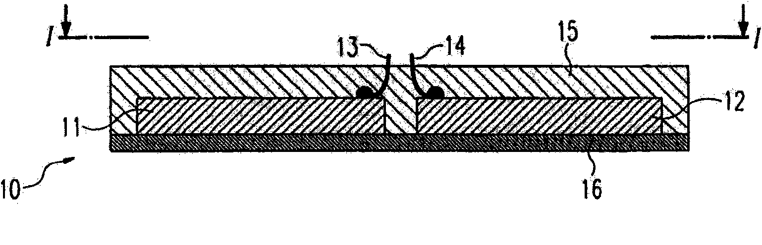
[0026] as from figure 1 and 2 As is known from , the neutral electrode comprises two usually metallic electrodes 11 , 12 which are placed on a carrier 15 and firmly connected thereto. The active surfaces of the electrodes 11, 12 that are not connected to the carrier or are not covered by the carrier, in figure 2 In the electrode state shown in , that is to say before its use, it is covered by a cover film 16 . as in figure 2 As indicated in , the cover film 16 can be made of a homogeneous material, which film has a defined electrical resistance. However, it is also possible to use individual contacts and resistors between them (which in turn can be designed as foils), so that a so-called defined resistor is formed between electrodes 13 and 14 .

[0027] Connecting lines 13 , 14 are provided for connection to an electrosurgical device, which are el...


PUM


Abstract

Neutral electrodes are known, having at least two electrodes electrically insulated from each other, the active surfaces whereof can be applied to a skin segment of a patient and having a cover film attached to the active surfaces and removed prior to applying to the skin segment. The invention proposes designing at least segments of the cover film having a defined electrical resistance, so that a defined resistance is created between the electrodes.

Description

technical field [0001] The invention relates to a neutral electrode according to the preamble of claim 1 and an electrosurgical device according to the preamble of claim 4 and also to a plastic material according to claim 7 Use of a thin film or ceramic thin film and a method for producing and operating a neutral electrode according to claim 8 . Background technique [0002] In electrosurgical devices it is known to connect different instruments to one or the same device. In order to adapt the electrosurgical device to the connected instrument, it is known, for example, from DE 4339049C2 to implement a code, for example, to inform the device of the code through the existing resistance in the instrument and the interface of the instrument on the electrosurgical device, so that it can be obtained from Read the data of the connected instruments in the comparison list and adjust the electrosurgical device accordingly. [0003] In many cases, monopolar instruments are used in e...

Claims


Application Information

Patent Timeline
Patent Type & Authority Applications(China)
IPC IPC(8): A61B18/14
CPCA61B18/14Y10T29/49204Y10T156/10A61B2018/00642A61B2018/00875B32B37/12B32B37/18B32B2307/202B32B2307/204B32B2457/00B32B2535/00
Inventor 迈克尔·赖克
Owner ERBE ELEKTROMEDIZIN GMBH
Why Eureka
Try Eureka