Wire clip

A wire buckle and fastener technology, which is applied to electrical components, coupling devices, circuits, etc., can solve the problems of falling off, unable to play the plug 42, and non-conforming specifications, and achieves flexible and convenient use and operation, no complicated production procedures, and component structure. simple effect

Inactive Publication Date: 2010-11-24
ACBEL POLYTECH INC
View PDF0 Cites 0 Cited by
  • Summary
  • Abstract
  • Description
  • Claims
  • Application Information

AI Technical Summary

Problems solved by technology

[0003] However, the shapes of the plugs 42 produced by various manufacturers on the market are slightly different, and the distance between the side of the plug 42 provided with the blade for plugging into the socket 51 and the other side is also very different. However, the two support arms 31 of the wire buckle of the prior art are fixed lengths, that is, the distance between the casing 50 and the connecting arms 32 is fixed, so only a plug 42 of a fixed size can be provided. When there are power cords 40 of different brands connected, it may be that the size specification of the plug 42 does not conform to the specification of the set wire buckle, so that the wire buckle cannot play its function of resisting and buckling to prevent the plug 42 from falling off, so it remains to be seen. solved problem

Method used


Image

  • Wire clip
  • Wire clip
  • Wire clip

Examples


Embodiment Construction

[0029] The above and other technical features and advantages of the present invention will be described in more detail below in conjunction with the accompanying drawings.

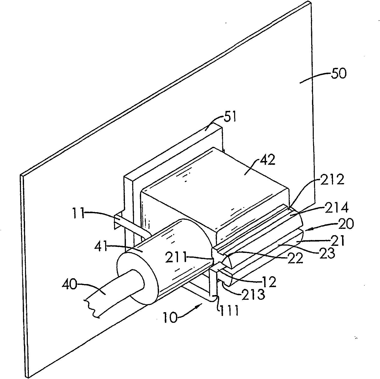
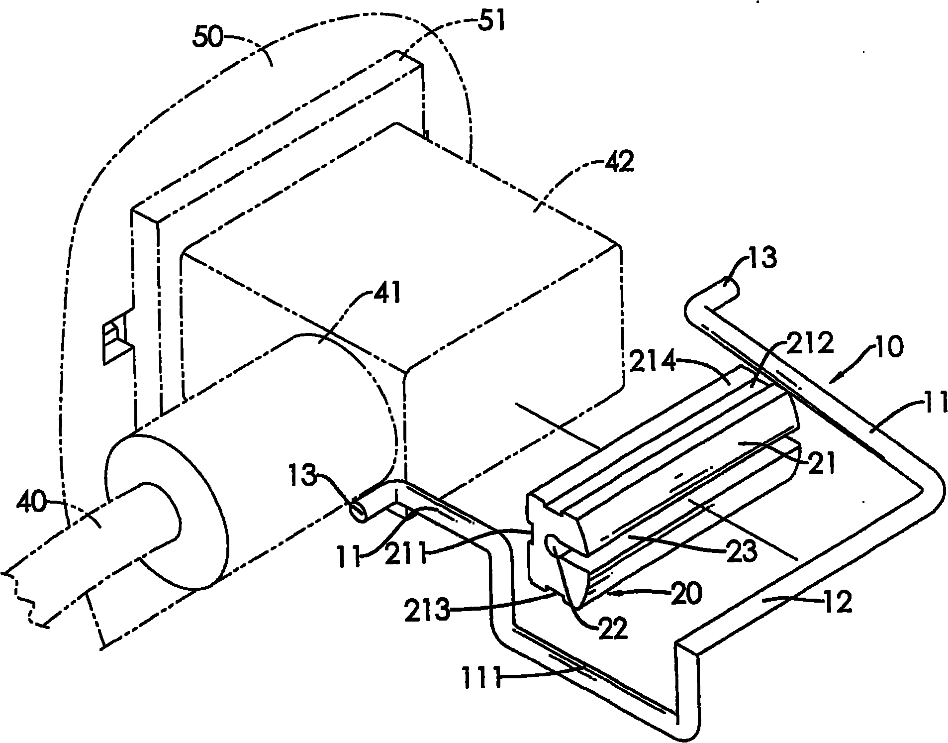
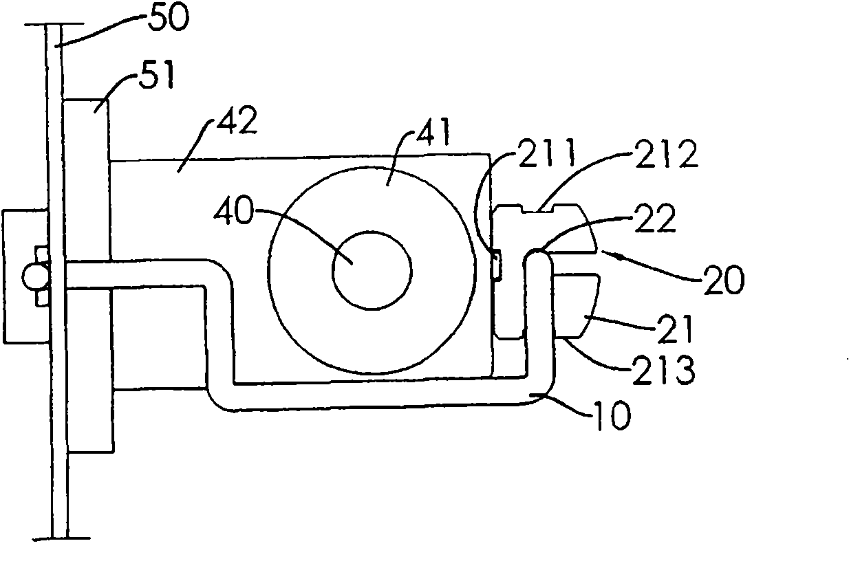
[0030] see figure 1 and figure 2 As shown, the wire buckle of the present invention includes a body 10 and a fastener 20, wherein:

[0031] The body 10 is formed by bending a rod, which can be a metal material (for example: stainless steel), and has two spaced support arms 11, and a connecting arm between one end of the two support arms 11 12, and the other end of the two support arms 11 is formed with a pivot joint 13, and the two support arms 11, the connecting arm 12 and the pivot joint 13 are located on the same plane, in addition to match the shape of the plug 42 shown in the figure, In a specific embodiment of the body 10, one support arm 11 is bent to form a concave portion 111, the concave portion 111 is designed according to the shape and position of the connecting portion 41 of the power cord...


PUM


Abstract

The invention relates to a wire clip, which comprises a body and a fastener. The body is provided with two alternatively arranged supporting arms and a connecting arm located between one end of one support arm and one end of the other support arm; pivot parts are respectively formed at the other ends of the two supporting arms and are connected on a casing with a socket in a pivoting mode; the fastener is of a cylinder, the external side face of the fastener is a butting face; an axial through hole penetrates through the cylinder, corresponds to the connecting arm and is connected with the connecting arm in a pivoting mode; and the radial distances of the center of the through hole corresponding to the butting face of the external side face of the fastener are different at different directions. Therefore, the butting surface can be regulated at different directions by rotating the fastener to apply on a plug, so as to achieve the purpose of providing stable plugging for plugs with different sizes.

Description

technical field [0001] The present invention relates to a wire buckle, in particular to a wire buckle that uses different distances between the wire buckle body and the outer abutment surface of the fastener to achieve a wire buckle capable of stably inserting plugs of different specifications. Background technique [0002] The cable tie is used in computer equipment. It is installed at the external socket of the power supply to fix the plug of the power cord and prevent the power cord from falling off due to accidental pulling, such as Figure 10 As shown, it is a wire buckle in the prior art. Its body 30 is bent from a stainless steel rod, and has two support arms 31, and a connecting arm 32 is formed between one end of the two support arms 31, one of which supports The arm 31 is bent to form a concave portion 311, the concave portion 311 is designed according to the shape of the connecting portion 41 of the power cord 40, and the other ends of the two supporting arms 31 ar...

Claims


Application Information

Patent Timeline
IPC IPC(8): H01R13/639
Inventor 陈宣宇林天文余柏勋黄家健
Owner ACBEL POLYTECH INC
Why Eureka
Try Eureka