
Color filter

A color filter and color filter film technology, applied in the field of color filters, can solve problems such as inconvenience, general products have no structure, and the improvement of light transmittance is limited.

Active Publication Date: 2010-11-24
E INK HLDG INC
View PDF4 Cites 16 Cited by
  • Summary
  • Abstract
  • Description
  • Claims
  • Application Information

AI Technical Summary

Problems solved by technology

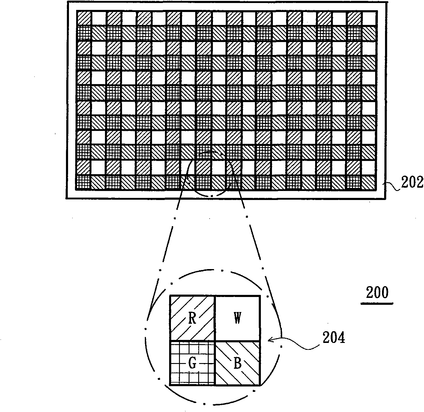
However, only by adding the white filter film W to the color filter 200, the improvement of the light transmittance of the color filter 200 is still limited.
[0006] This shows that above-mentioned existing color filter obviously still has inconvenience and defect in structure and use, and urgently needs to be further improved.
In order to solve the above-mentioned problems, the relevant manufacturers have tried their best to find a solution, but no suitable design has been developed for a long time, and the general products do not have a suitable structure to solve the above-mentioned problems. This is obviously related. The problem that the industry is eager to solve

Method used


Image

  • Color filter
  • Color filter
  • Color filter

Examples


Embodiment Construction

[0044] In order to further explain the technical means and effects of the present invention to achieve the intended purpose of the invention, the specific implementation, structure, characteristics and effects of the color filter proposed according to the present invention will be described below in conjunction with the accompanying drawings and preferred embodiments. , as detailed below.

[0045]The following will take a reflective display as an example to illustrate the application of the color filter of the present invention, but it is not intended to limit the present invention. Those skilled in the art should know that the color filter of the present invention can also be applied to other types of displays.

[0046] image 3 It is a schematic cross-sectional view of a reflective display in an embodiment of the present invention. Please refer to image 3 As shown, the reflective display 300 includes a reflective electrode array substrate 310 , a display medium layer 320...


PUM


Abstract

The invention relates to a color filter comprising a base plate, a plurality of pixel units and a light-transmitting electrode layer, wherein the base plate is provided with a plurality of pixel areas, and each pixel area comprises a plurality of first sub-pixel areas and a second sub-pixel area; the pixel units are respectively configured in the corresponding pixel areas, and each pixel unit comprises a plurality of color filter films and a white filter film; in each pixel unit, the color filter films are respectively configured in the corresponding first sub-pixel areas, the white filter film is configured in the second sub-pixel area, and the area of the white filter film is larger than that of each color filter film so that the light-transmitting rate of the color filter is enhanced; and the light-transmitting electrode layer is configured on the pixel units.

Description

technical field [0001] The invention relates to a color filter, in particular to a color filter with high transmittance. Background technique [0002] A reflective display uses reflected incident light as a light source for displaying images on the display. Since the reflective display does not need to be equipped with a backlight source, the power consumption of the components is reduced, and the entire display can be designed to be thinner and lighter, so it has been highly valued in the display industry in recent years. [0003] In color reflective displays, the purpose of displaying color images is mostly achieved by installing color filters. figure 1 It is a schematic diagram of light incident on an existing conventional color reflective display. Please refer to figure 1 As shown, the color reflective display 100 includes a color filter 102 , a display medium layer 104 and a reflective electrode array substrate 106 . The light L will first pass through the color fil...

Claims


Application Information

Patent Timeline
IPC IPC(8): G02F1/1335
Inventor 萧博文蔡渊智陈礼廷刘全丰辛哲宏
Owner E INK HLDG INC
Learn More