Stator coil and method of manufacturing the same

A technology for stator coils and manufacturing methods, which is applied in the field of wave winding stator coils and its manufacturing, which can solve the problems of wire damage, large angle, discharge of coil end 4a, etc., to reduce damage, increase floor area, and improve reliability Effect

Active Publication Date: 2010-11-17
NITTOKU ENG CO LTD +1
View PDF6 Cites 7 Cited by
  • Summary
  • Abstract
  • Description
  • Claims
  • Application Information

AI Technical Summary

Problems solved by technology

Therefore, the coil end portion 4a existing on the inner side must draw a large arc to overlap the coil end portion 4a on the outer diameter side in the axial direction of the core 6, so it is difficult to fully discharge the coil end portion 4a as a whole. The outer diameter side of the stator core 6
In addition, there is also a problem that if the portion drawn with a large arc remains on the inner diameter side end face of the core, it will interfere with the coil end of the other stator coil assembled later.
That is, since the embedding device (not shown) converts the directions of the plurality of coil side portions 4c located in the plane into approximately right angles and erects them, the conversion angle is relatively large, and may affect the configuration of the coil side portions 4c when erected. The wire of coil 4 caused damage
The thicker the wire material constituting the wave winding coil 4, the more likely this damage will increase.

Method used


Image

  • Stator coil and method of manufacturing the same
  • Stator coil and method of manufacturing the same
  • Stator coil and method of manufacturing the same

Examples


Embodiment Construction

[0034] Hereinafter, the mode for carrying out the present invention will be described in detail with reference to the drawings.

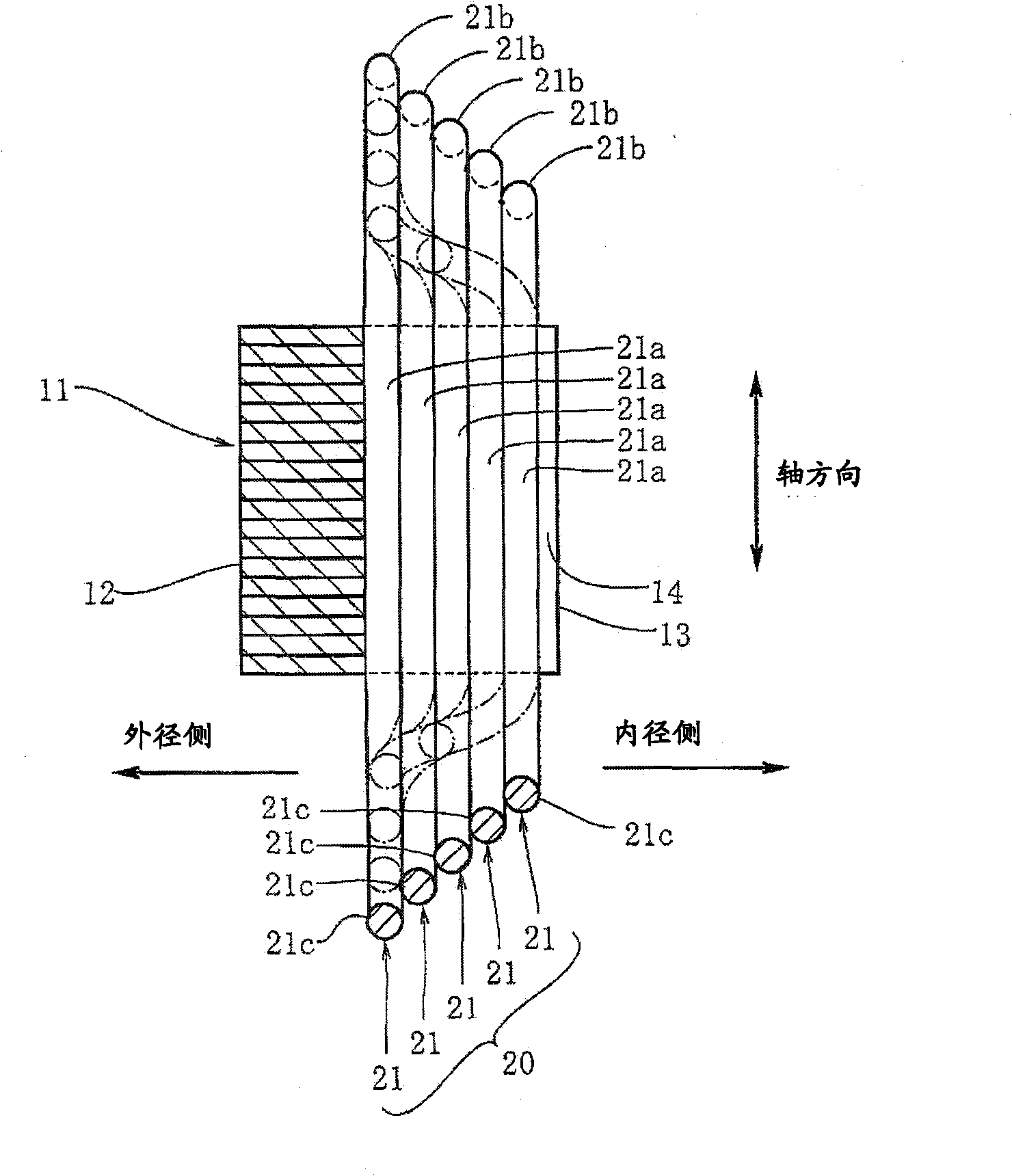
[0035] Figure 4 The perspective view which shows the stator 10 which assembled the stator coil 20 of this invention to the stator core 11. The stator core 11 is made of a magnetic material having an annular portion 12 and a plurality of teeth 13 protruding from the inner peripheral surface of the annular portion 12 toward the center of the annular portion 12 , and between the plurality of teeth 13 A plurality of slots 14 are formed for accommodating coil side portions 21 a described later of the stator coil 20 . The stator core 11 of the present embodiment represents a laminated stator core formed by laminating and fixing core plates having a predetermined thickness of annular portions 12 and teeth 13 to a predetermined thickness.

[0036] The stator coil 20 of the present invention is a coil before being assembled into the core 11, such as fig...


PUM


Abstract

The invention provides a stator coil (20), which can realize the high occupying rate of the coil terminal part at nearby of the core end-face and reduce the damage produced during assembling. The stator coil is formed continuously by a plurality of unit wave winding coils (21) in the radial direction, the unit wave winding coil makes the coil edge parts (21a) inserted in the slot (14) of the stator core (11) and the coil terminal parts (21b, 21c) protruding from the axial end-face of the stator core (11) to alternatively form at the circumference direction in a crawl bending mode to form a ring winding coil. The diameter of the circle pictured by a coil terminal part (21b) at one side end of the coil edge part is different from the diameter of the circle pictured by the coil terminal part(21c) of the other side end. The manufacturing method is to alternately enwind the wire (17) alternately on the first and second clamping parts, so as to make the wire to be crawl bending and winding.

Description

technical field [0001] The present invention relates to stator coils used in rotating electric machines. More specifically, the present invention relates to a wave winding stator coil in which coil sides inserted into slots of a stator core and coil ends protruding from the slots are alternately formed, and a method for manufacturing the same. Background technique [0002] Conventionally, the stator of a rotating electrical machine has a cylindrical stator core and a stator coil, wherein the stator core has a plurality of teeth (magnetic poles) arranged radially and protruding in the inner diameter direction and a plurality of slots opened therebetween; the stator coil, Assembled on the core by receiving the coil side in the slot. As for the assembly of the stator coil, a so-called embedding method is known, in which the stator coil and the stator core are manufactured separately in advance, and the coil is accommodated in each slot of the core. Also, a wave winding method...

Claims


Application Information

Patent Timeline
Patent Type & Authority Applications(China)
IPC IPC(8): H02K3/04H02K15/085H02K1/16
Inventor 阿纳尔多·维亚纳·德·萨梶田效
Owner NITTOKU ENG CO LTD
Why Eureka
Try Eureka