
Shell ring assembly device for assembly of tower body of wind power generation iron tower

A technology for tower body and power unit of iron tower, applied in auxiliary devices, auxiliary welding equipment, welding/cutting auxiliary equipment, etc. question

Inactive Publication Date: 2010-11-17
WEIFANG WUZHOU WIND POWER EQUIP
View PDF6 Cites 37 Cited by
  • Summary
  • Abstract
  • Description
  • Claims
  • Application Information

AI Technical Summary

Problems solved by technology

[0003] The technical problem to be solved by the present invention is: to provide a barrel joint assembly device for wind power generation iron tower body assembly, so as to solve the difficulty in adjusting the coaxiality of multiple sets of barrel joints when the wind power generation iron tower body is assembled, and the operator is laborious. Technical issues with high intensity and low work efficiency

Method used


Image

  • Shell ring assembly device for assembly of tower body of wind power generation iron tower
  • Shell ring assembly device for assembly of tower body of wind power generation iron tower
  • Shell ring assembly device for assembly of tower body of wind power generation iron tower

Examples


Embodiment 1

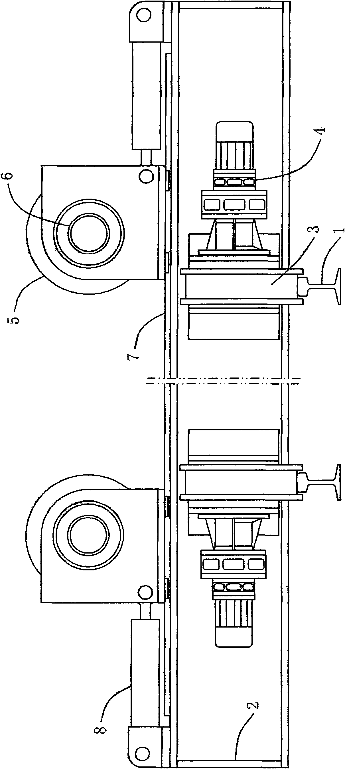
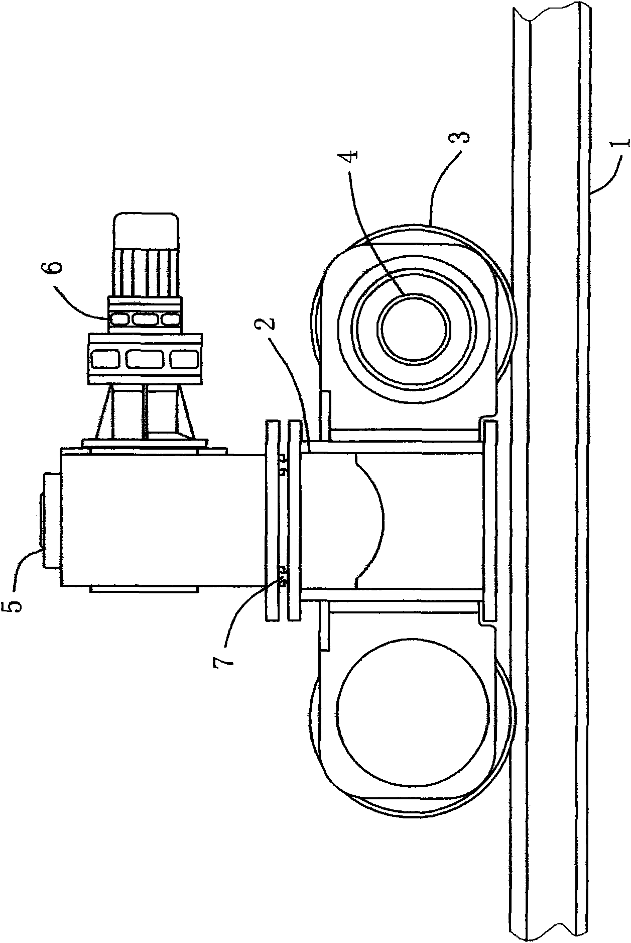
[0027] Such as figure 1 , figure 2 and Figure 4 As shown, a barrel joint pairing device for wind power tower body assembly includes at least two groups of pairing units that are slidably installed on horizontal rails 1; The roller frame 2 on the roller frame 2 is provided with a roller 3 matching with the horizontal track 1, and the roller frame 3 is arranged on two sides of the roller frame 2 or the bottom surface of the roller frame 2, and the roller frame The upper end surface of 2 is provided with a slide rail 7, which is perpendicular to the extension direction of the horizontal rail 1; two runners 5 for supporting the cylinder joint, and the two runners 5 are mounted on the on rail 7.

[0028] The two runners 5 are respectively connected with a force applying device, the force applying direction of the force applying device is consistent with the extension direction of the slide rail 7, one end of the force applying device is hinged on the roller frame 2, and the ot...

Embodiment 2

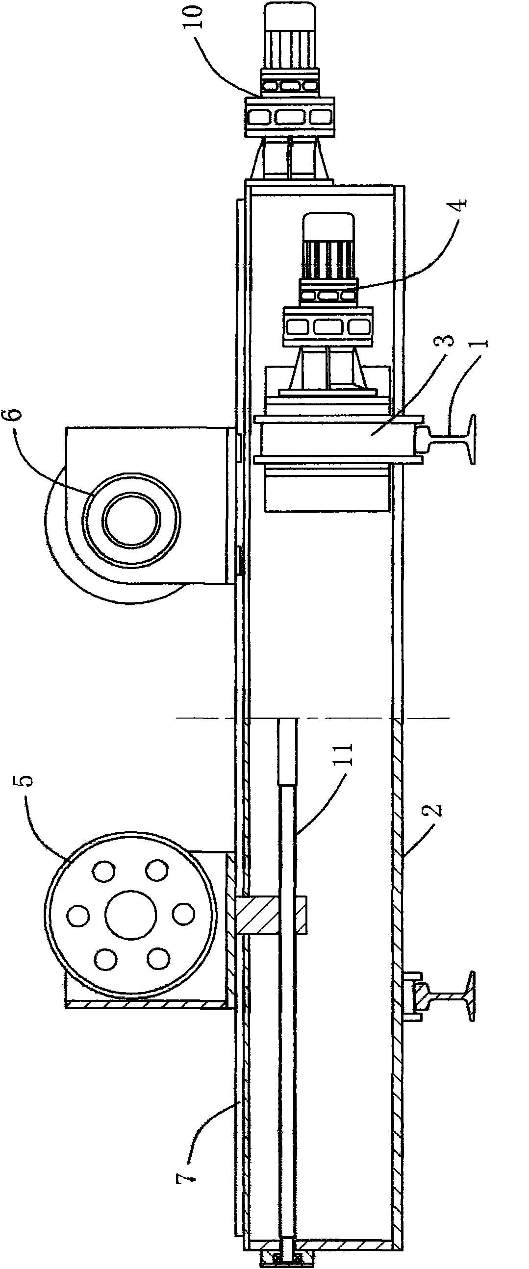
[0033] Such as image 3 As shown, a barrel joint assembly device for wind power generation iron tower tower body assembly, its structure is basically the same as that of Embodiment 1, the difference is that: the two runners 5 are respectively threaded to be driven by the first power device On the screw 11, the screw 11 is rotatably mounted on the roller frame 2, the screw 11 is consistent with the extension direction of the slide rail 7, the screw 11 is provided with forward and reverse threads, the first power unit It is preferably the first motor reducer 10 .

[0034] Considering the frequency of use and cost, the first power unit can be replaced by a hand wheel, and the center height of the barrel joint can be adjusted by manually operating the distance between the two runners 5 .

[0035] It works as follows:

[0036] Such as Figure 5 and Figure 6 As shown, four groups of pairs of units are arranged on the horizontal track, which are successively the first group of p...


PUM


Abstract

The invention discloses a shell ring assembly device for the assembly of a tower body of a wind power generation iron tower, which belongs to the technical field of wind power generation iron tower machining equipment. The shell ring assembly device comprises at least two groups of assembly units which are arranged on horizontal rails in a sliding way, and two rotating wheels for bearing shell rings, wherein each assembly unit comprises a roller frame arranged on the horizontal rails; the roller frame is provided with a roller matched with the corresponding horizontal rails; the upper end face of the roller frame is provided with a sliding rail which is vertical to the extension direction of the horizontal rails; and the two rotating wheels are oppositely arranged on the corresponding sliding rails in the sliding way. The shell ring assembly device solves the technical problems, in the assembly of the tower body of the wind power generation iron tower, that the coaxiality of a plurality of groups of shell rings is difficult to regulate, that the labor intensity of operators is high and that the working efficiency is low, has a rational structure and is widely applied to the machining process of the wind power generation iron tower.

Description

technical field [0001] The invention relates to the technical field of wind power generation iron tower processing equipment, in particular to a barrel joint pairing device used for wind power generation iron tower body assembly. Background technique [0002] The tower body of the wind power tower is welded by multiple sets of tube sections. Due to the relatively large diameter of the tower body and the relatively thick wall thickness of the tube sections, it is relatively difficult to weld the tube section groups during the manufacturing process. The traditional barrel joint method is as follows: first hoist the barrel joints that need to be assembled on a simple assembly tool, and then use the method of pulling the horse and punching the clips to perform the assembly. After a point is aligned, it needs to be turned over by driving. The cylinder joints, and then point to another point, and cycle in turn, thus completing the pairing of the cylinder joints. This traditional ...

Claims


Application Information

Patent Timeline
IPC IPC(8): B23K37/053
Inventor 任吉华刘志强王海龙袁媛
Owner WEIFANG WUZHOU WIND POWER EQUIP
Learn More