Eureka AIR delivers breakthrough ideas for toughest innovation challenges, trusted by R&D personnel around the world.

Direct current permanent magnetic upper wheel motor

A permanent magnet type, sky wheel technology, applied in the direction of magnetic circuit shape/style/structure, magnetic circuit static parts, etc., can solve the problems of inconvenient maintenance, mechanical friction loss, waste of electric energy, etc., to extend the maintenance period, save The effect of reducing power and operating costs

Inactive Publication Date: 2010-11-10
沈阳昊灵达新技术研究所有限公司
View PDF3 Cites 3 Cited by
  • Summary
  • Abstract
  • Description
  • Claims
  • Application Information

AI Technical Summary

Problems solved by technology

[0002] The pumping unit currently used in oil wells drives the pumping unit to work through the rotation of the sky wheel, but the sky wheel needs to be driven by a motor, which has mechanical friction and wear, and wastes electric energy, which is inconvenient to maintain and high in operating costs.

Method used


Image

  • Direct current permanent magnetic upper wheel motor
  • Direct current permanent magnetic upper wheel motor

Examples


Embodiment Construction

[0014] The embodiments of the present invention will be described in detail below in conjunction with the accompanying drawings, but the protection scope of the present invention is not limited by the embodiments.

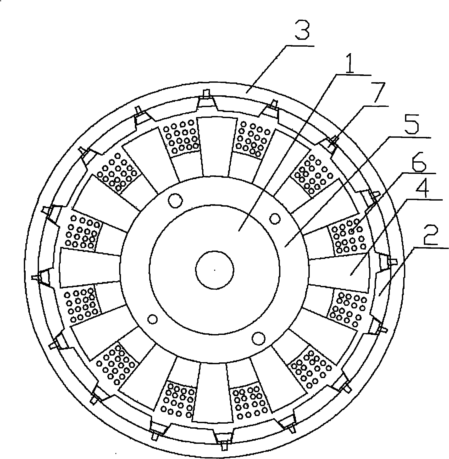
[0015] As shown in the figure, a DC permanent magnet sky wheel motor of the present invention is composed of the following structure: the stator silicon steel sheet 4 is fixed on the main shaft through the stator inner ring locking sheet 5, and the stator silicon steel sheet 4 is wound with a coil winding 6 , there is a permanent magnet 2 between the stator silicon steel sheet 4 and the outer rotor ring 3, three stator silicon steel sheets 4 and four permanent magnets 2 form a group, and the distance between the top surfaces of adjacent permanent magnets 2 is the same Half of the distance between adjacent stator silicon steel sheets 4, the first stator silicon steel sheet 4 in each group is directly opposite to the first permanent magnet 2, the second permanent magn...


PUM


Abstract

The invention relates to a motor, in particular to a direct current permanent magnetic upper wheel motor for use in an oil field pumping unit. The direct current permanent magnetic upper wheel motor has a structure that: a stator silicon steel sheet is fixed on a spindle by a stator inner ring locking plate; coil windings are wound on the stator silicon steel sheet; and a permanent magnet is arranged between the stator silicon steel sheet and an outer rotor ring. The invention has the advantages that: the motor is suitable for the power outputs of various lifting machines and replaces the mechanical transmission parts of the conventional lifting machines; the output power of the motor act directly to improve working conditions; zero friction and zero loss of the machines are realized; as mechanical friction and loss are avoided, electric energy is saved by about 40 to 60 percent; the maintenance period is prolonged; and as the repair and maintenance cost of the machines are avoided, the equipment operation cost is reduced considerably.

Description

technical field [0001] The invention relates to a motor, in particular to a DC permanent magnet sky wheel motor used in an oil well pumping unit. Background technique [0002] The pumping unit currently used in oil wells drives the pumping unit to work through the rotation of the sky wheel, but the sky wheel needs to be driven by a motor, which causes mechanical friction and wear, wastes electric energy, inconvenient maintenance, and high equipment operating costs. Contents of the invention [0003] In order to solve the above technical problems, the present invention provides a DC permanent magnet sky wheel motor, the purpose of which is to prolong the maintenance period and reduce the operation cost of the equipment. [0004] In order to achieve the above-mentioned purpose, a DC permanent magnet sky wheel motor of the present invention is composed of the following structure: the stator silicon steel sheet is fixed on the main shaft through the stator inner ring locking s...

Claims


Application Information

Patent Timeline
Patent Type & Authority Applications(China)
IPC IPC(8): H02K1/17
Inventor 夏德权魏玉贤宋微马文天董昭刚张跃明余中红徐晓辉
Owner 沈阳昊灵达新技术研究所有限公司
Why Eureka
Eureka Blog
Learn More