
Scanning type LED display device and method for eliminating forward moving hidden brightness thereof

A display device and scanning technology, which is applied in lighting devices, static indicators, electric lamp circuit layout, etc., can solve the problems of inconspicuous, bright light, and affecting the screen display effect of the conductive LED.

Inactive Publication Date: 2012-05-23
苏州卫优知识产权运营有限公司
View PDF0 Cites 0 Cited by
  • Summary
  • Abstract
  • Description
  • Claims
  • Application Information

AI Technical Summary

Problems solved by technology

But this design has fatal disadvantages: complex circuit, low hardware utilization, and huge cost
Because the more the number of light-emitting LEDs, the more current paths, the smaller the current flowing through each path, and the faster the discharge speed, so that each conduction LED is dimly lit and not obvious; when only m+1 When an LED emits light, the light-emitting time is relatively long, which causes the LED to emit light brightly, and a strong hidden brightness appears.
[0011] When the LED display screen has the problem of line hidden brightness, it will cause the LEDs that should not be bright to light up around the LEDs that should be on in the display screen, thus affecting the display effect of the screen.

Method used


Image

  • Scanning type LED display device and method for eliminating forward moving hidden brightness thereof
  • Scanning type LED display device and method for eliminating forward moving hidden brightness thereof
  • Scanning type LED display device and method for eliminating forward moving hidden brightness thereof

Examples


Embodiment Construction

[0044] The present invention will be described in detail below with reference to the drawings.

[0045] The scanning LED display device of the present invention is mainly used to display images, texts and other information transmitted by various peripherals (such as computers, players, offline systems, etc.), but is not limited to this.

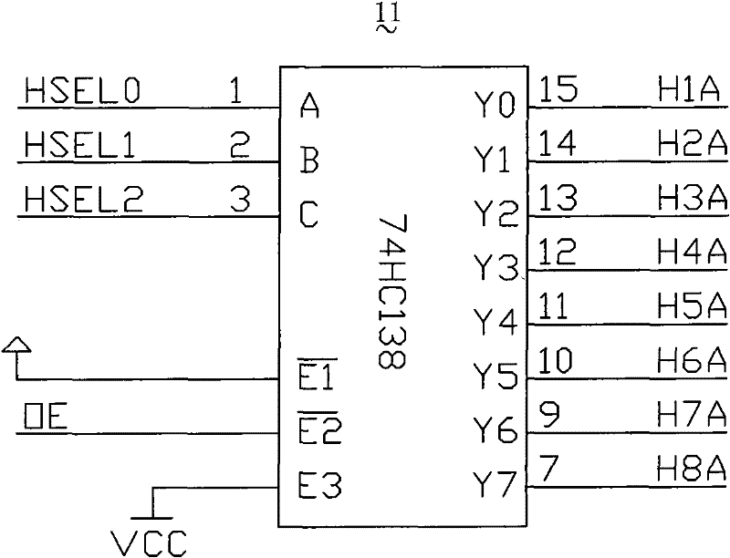
[0046] Such as figure 1 As shown, the scanning LED display device 10 according to the first embodiment of the present invention mainly includes a row decoder 11, a row driver 12, and a number of rows of LEDs (see figure 1 Reference numeral 13), column driver 14, cascade circuit (not shown), discharge device 16A, etc. are described in detail below.

[0047] The rows of LEDs can be arranged in a matrix. In the case of a relatively large display screen, the LEDs can be arranged on a number of unit boards (such as circuit boards) and then assembled into a large display screen; In the case of, it can also be directly arranged on a substrate, such as a ...


PUM


Abstract

The invention relates to a scanning type LED display device and a method for eliminating forward moving hidden brightness thereof, wherein the scanning type LED display device comprises a plurality of row drivers, line drivers, a plurality of line LEDs and a discharging device, wherein the output end of the row drivers is connected with the discharging device. The method for eliminating forward moving hidden brightness comprises the following steps: 1) detecting the row selection signal variation of the time intervals between the row driving time and the line driving time of some row of LEDs of the scanning type LED display device; and 2) setting the discharging time of the discharging device to be smaller than the time intervals, generating a discharging control signal when the row selection signal variation of the scanning type LED display is detected so that electric charges on the output end of the row drivers on the positive electrodes of the front row of LEDs are discharged and connected for eliminating the hidden brightness generated by the front row of LEDs when or before a row of LEDs are lightened.

Description

[0001] This application is a divisional application for "scanning LED display devices and methods to eliminate their forward fading light". The original patent application was filed on January 8, 2007, the application number is 200710000050.X, and the invention patent name is " Scanning LED display device and the method to eliminate the fading light on the front". 【Technical Field】 [0002] The invention relates to an LED display device, in particular to a scanning LED display screen; in addition, the invention also relates to a method for eliminating the forward fading of the LED display device. 【Background technique】 [0003] Light Emitting Diode (LED) in English is Light Emitting Diode (LED), its basic structure is a piece of electroluminescent semiconductor material, placed on a leaded shelf, and then sealed with epoxy resin around, when it is in a forward working state (That is, the positive voltage is applied to both ends). When the current flows from the LED anode to the ca...

Claims


Application Information

Patent Timeline
Patent Type & Authority Patents(China)
IPC IPC(8): G09G3/32G09G3/20H05B33/08H05B33/14H05B37/02H01L27/32H01L51/50H05B44/00
CPCY02B20/42Y02B20/343Y02B20/30Y02B20/40
Inventor 邵寅亮
Owner 苏州卫优知识产权运营有限公司
Learn More