
Filter element for water purifier

A technology for water purifiers and filter elements, which is applied in the direction of filtration separation, gravity filters, chemical instruments and methods, etc., can solve the problems of uneven filtration effect of the filter element layer, affect the popularization of water purifiers, and affect the filtration effect, etc. After-sales service cost, easy replacement of filter element, good effect

Inactive Publication Date: 2010-10-20
杜也兵
View PDF5 Cites 0 Cited by
  • Summary
  • Abstract
  • Description
  • Claims
  • Application Information

AI Technical Summary

Problems solved by technology

No matter how big it is, it's hard to operate
Even if a small-diameter post-processing filter element is set in the remaining space around a group of main independent filter elements, the height of the filter element cannot be increased due to the height limit of the whole machine, and its correspondingly too small volume cannot match the main filter element, resulting in extremely short life. The vast majority of water purifiers adopt a single-row low configuration mode with fewer filter elements and a larger diameter; mid-range and high-end models adopt a single-row high configuration mode with small diameter and multiple filter elements
In addition, if the vertical configuration of the filter element is changed to a horizontal configuration, although it is more convenient to extract the filter element, due to the influence of gravity, the filtering effect of the cross-section of the filter element layer is not uniform, especially for the filter layer using activated carbon filter material. Material throwing and tumbling space
When it is placed horizontally, due to the weight of the filter material itself, it is arranged in an upper small and lower large arrangement, which directly affects the filtering effect.
Above-mentioned defect and deficiency have a strong impact on the popularization of water purifier

Method used


Image

  • Filter element for water purifier
  • Filter element for water purifier
  • Filter element for water purifier

Examples


Embodiment Construction

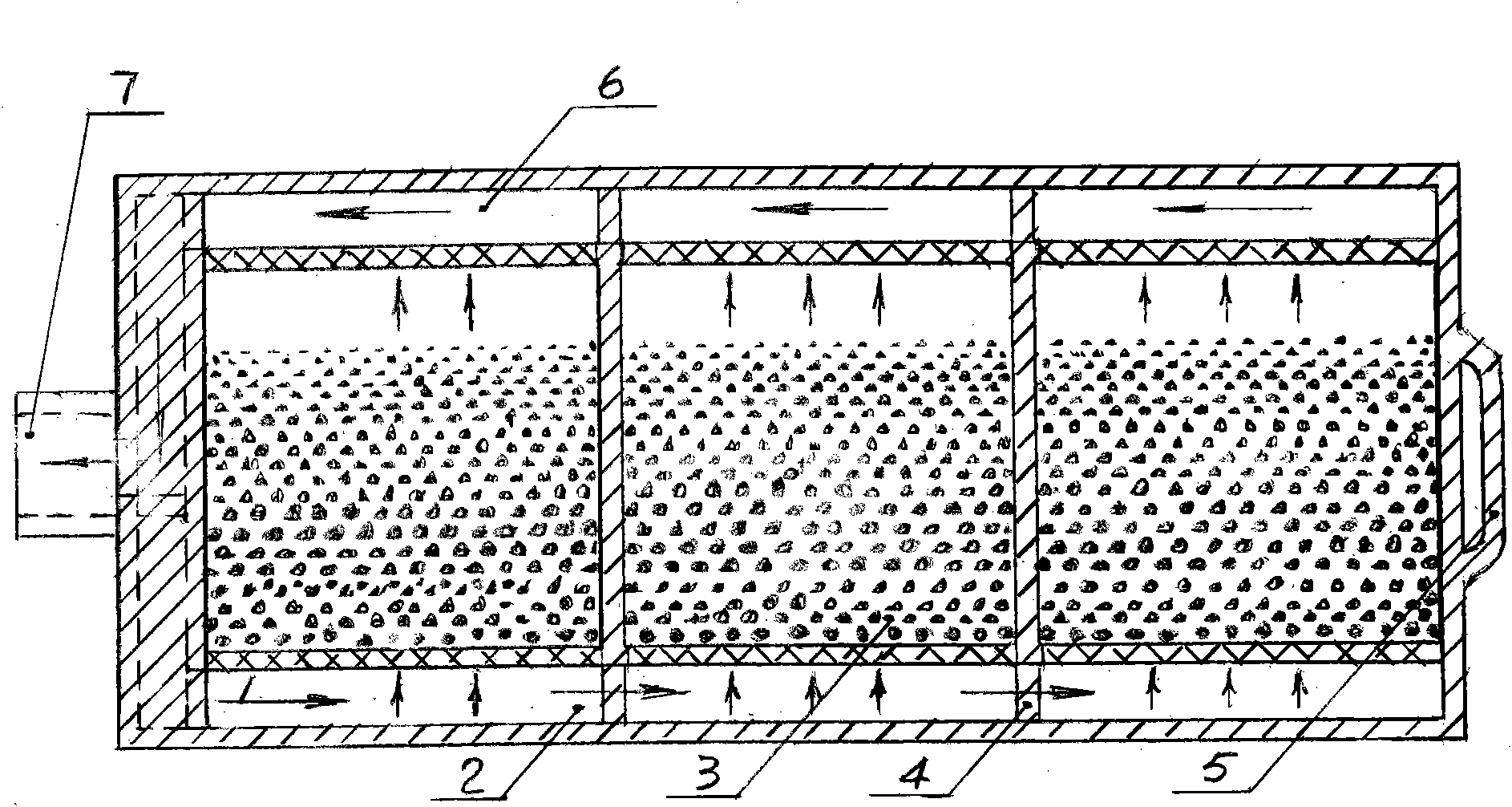
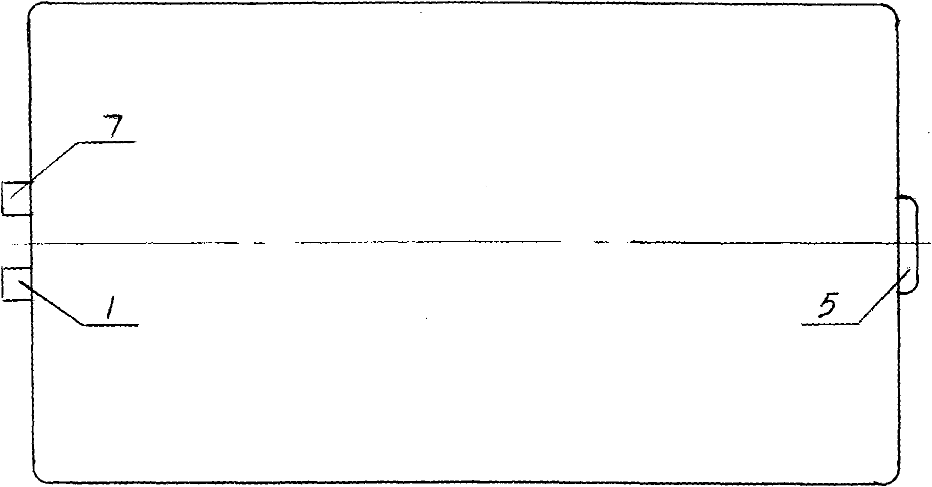
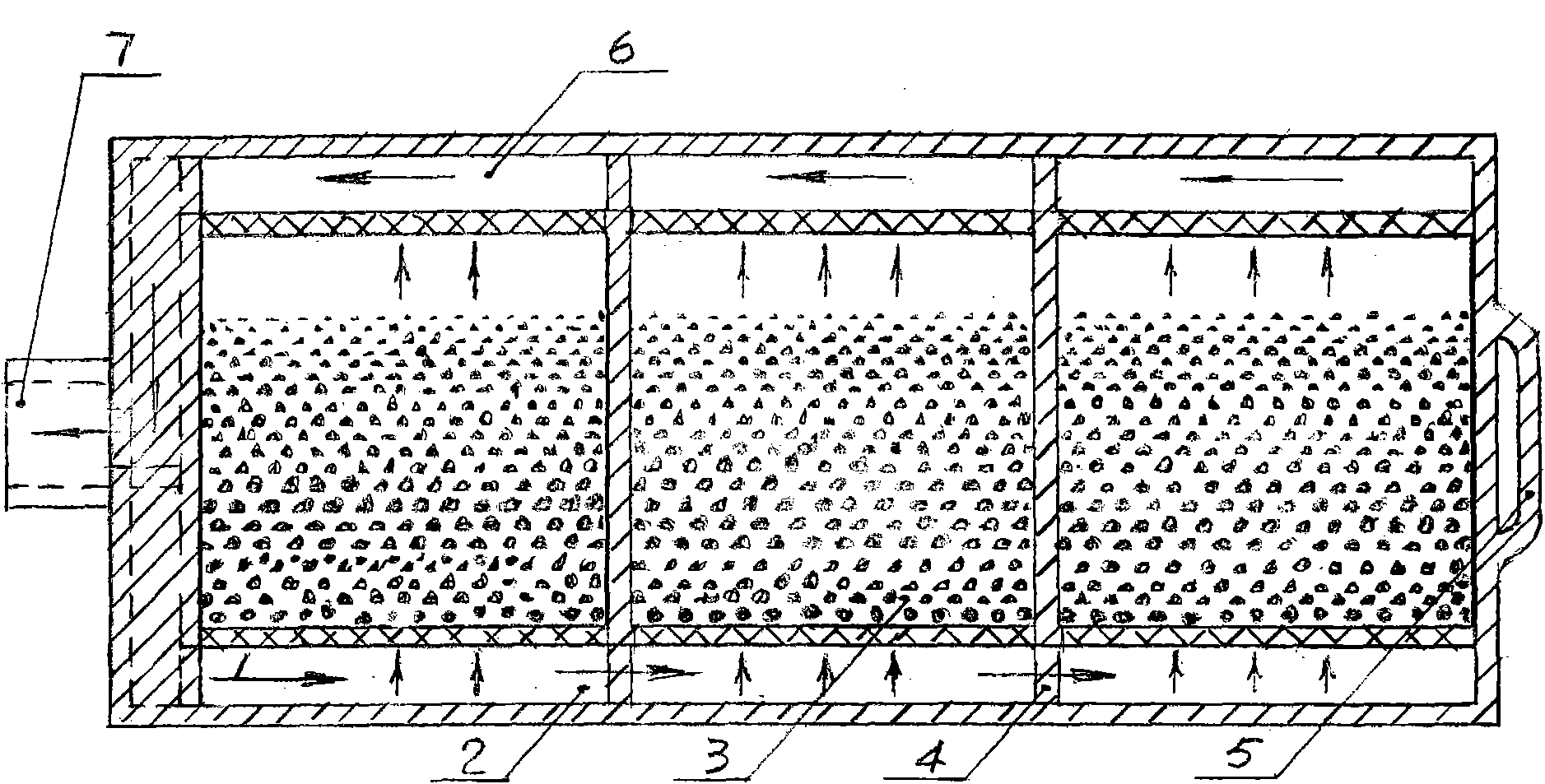
[0016] figure 1 , figure 2 A preferred embodiment of the present invention is shown. The water inlet and outlet 1 and 7 of the flat filter element are located on the same side, and are sealed and docked with the horizontal butt joint water inlet in the water inlet and outlet pipelines of the water purifier. Take out the filter element, rotate it 180 degrees, and then push it into the water purifier's horizontal docking port for sealing and docking to realize the second installation method of the filter element.

[0017] As far as the filter element adopting the horizontally placed filter element mode and the activated carbon filter material is concerned, the filter layer frame 4 for placing the activated carbon filter material 3 is provided with a plurality of independent small compartments, and the same amount of activated carbon filter material will be placed in each small compartment and a certain amount of space will be reserved. The large floating space meets the unifo...


PUM


Abstract

The invention relates to water treatment industry, in particular to the aspects of depth-type filtration and purification of drinking water. The invention discloses a filter element for a water purifier, wherein the water inlet and the water outlet of the filter element are arranged on the symmetrical alternative positions relative to the symmetric center. The invention has the following advantages: the back flush of the filter element is relatively thorough and has good effect, thus well preventing secondary pollution to the filter element, and impurities can be discharged from a water purification pipeline directly, thus the back flush effect is absolutely clear. As the filter element can be replaced conveniently, a user can purchase the filter element and replace the filter element by self, thus being benefit for the popularization of the water purifier, avoiding the inconvenience caused by the fact that the filter element can be replaced only by professionals and service expenditure, correspondingly reducing after service cost of the water purifier and the filter element and facilitating remote users.

Description

technical field [0001] The invention relates to the water treatment industry, and specifically relates to the deep filtration and purification of drinking water. Background technique [0002] At present, the use of water purifiers has been popularized to a certain extent in China. When using water, the water purifier is used to deeply filter the impurities in the water and water pipelines, which better protects the health of users. Due to the high cost of purchasing and using water purifiers, among all types of models, water purifiers with medium and low prices are more popular. However, along with the popularization of water purifiers, their defects and deficiencies in application are gradually exposed: after the filter element of the water purifier is used for a period of time, the filter element filter material is gradually blocked by impurities and adsorbed on the outer surface of the filter material As a result, the filtering and adsorption effects are significantly r...

Claims


Application Information

Patent Timeline
Patent Type & Authority Applications(China)
IPC IPC(8): B01D24/16
Inventor 杜也兵冉伊虹
Owner 杜也兵
Learn More