Actuating drive for bidirectional actuator

A technology of servo drive device and actuator, applied in valve device, valve operation/release device, charging system, etc., can solve problems such as short actuation time

Active Publication Date: 2010-10-13
MAHLE INT GMBH
View PDF2 Cites 13 Cited by
  • Summary
  • Abstract
  • Description
  • Claims
  • Application Information

AI Technical Summary

Problems solved by technology

In addition, relatively short actuation times must be achieved
Similar problems can also occur with other components of the exhaust system

Method used


Image

  • Actuating drive for bidirectional actuator
  • Actuating drive for bidirectional actuator
  • Actuating drive for bidirectional actuator

Examples


Embodiment Construction

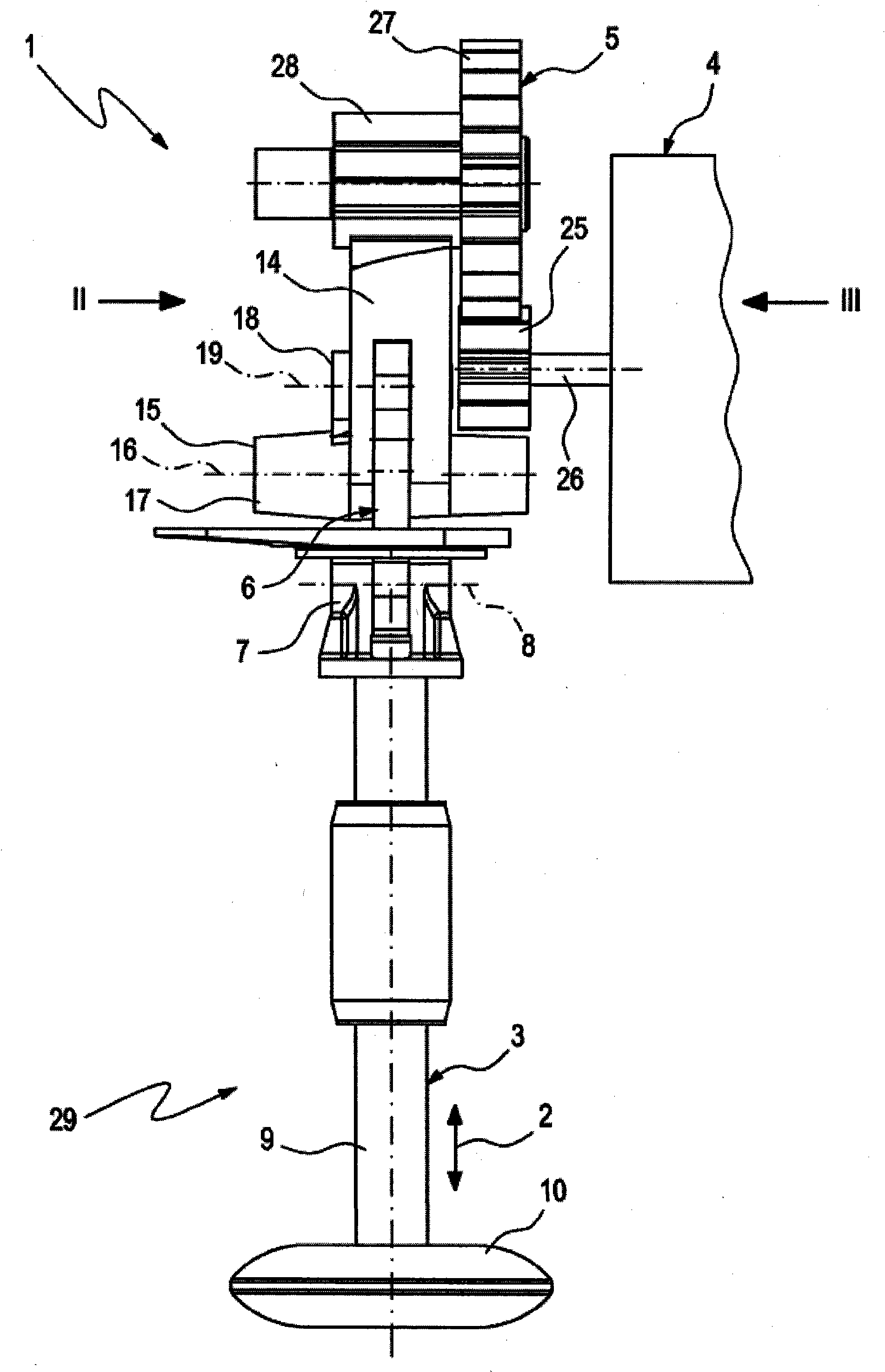
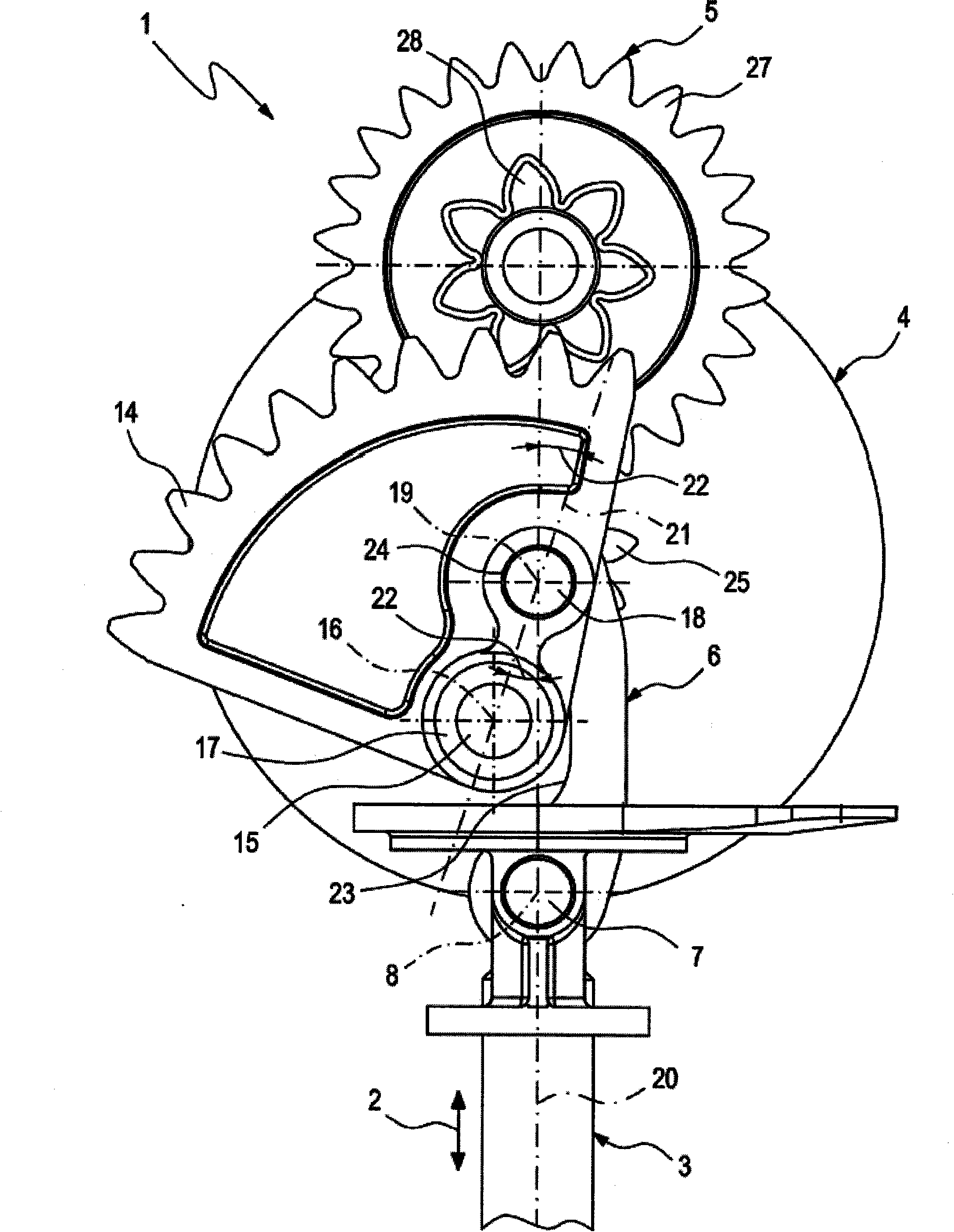
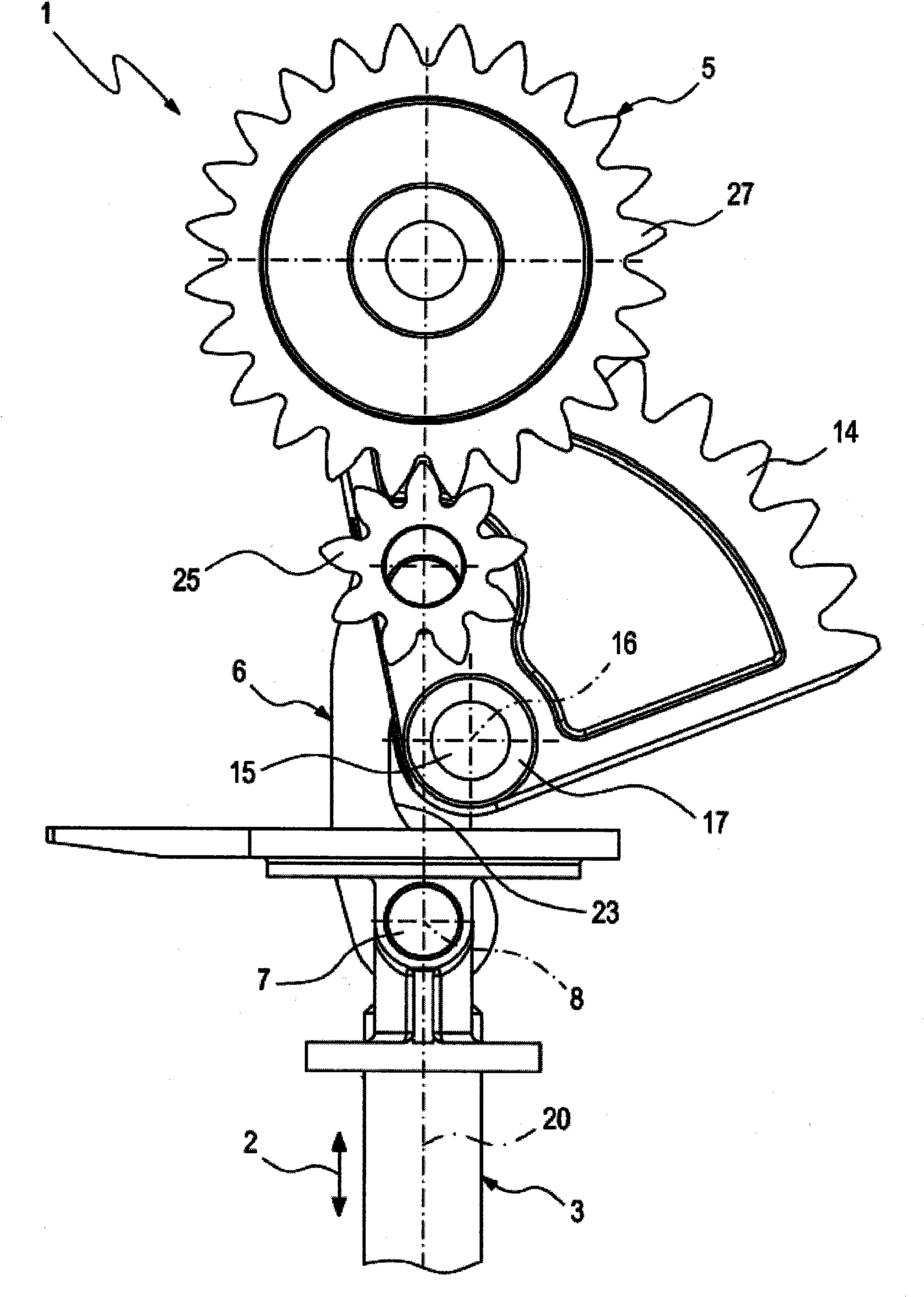
[0017] according to Figure 1-4 , a servo drive device 1, with which the actuator 3 can be driven, the actuator can be adjusted in both directions according to the double arrow 2, the device includes a motor 4, a gear device 5 and a crank connecting rod 6. The crankshaft connecting rod 6 can be connected to the actuator 3 in a meshing manner via a first crankshaft connecting rod bearing 7 . Here, the corresponding first crank-rod bearing shaft is referenced 8 . In the assembled state shown, the crank rod 6 is engaged with the actuator 3 via its first crank rod bearing 7 . exist Figure 1-3 In the embodiment shown, the actuator 3 is a valve assembly 9 carrying a valve body 10 . according to Figure 4 In the embodiment shown in the figure, the actuator 3 is used to drive the reciprocating lever (return lever) 11, which in turn is connected to the valve body 12 in a rotationally fixed manner, itself rotatably mounted about the axis of the rotating shaft 13, and The valve bod...


PUM


Abstract

The invention relates to an actuating drive (1) for an actuator (3), which can be adjusted bidirectionally, in particular for an exhaust gas recirculation device (29) or for an exhaust gas turbocharger (30), comprising an electric motor (4), a toggle lever (6), which can be connected in an articulated way to the actuator (3) via a first toggle lever bearing (7), and a gear mechanism (5), which connects the electric motor (4) to the toggle lever (6). The gear mechanism (5) has a gearing element (14), which is supported on the output side in a pivot bearing (15) and on which the toggle lever (6) is supported in an articulated way via a second toggle lever bearing (18). In a starting state of the actuating drive (1), which is associated with a starting position of the actuator (3), an angle (22) between a first straight line (20), which extends through the first toggle lever bearing (7) and through the second toggle lever bearing (18), and a second straight line (21), which extends through the pivot bearing (15) and through the second toggle lever bearing (18), is acute.

Description

technical field [0001] The invention relates to an actuating drive for a bidirectionally adjustable actuator. The invention also relates to an exhaust gas recirculation device or an exhaust gas turbocharger equipped with an actuating drive as described above. Background technique [0002] In order to be able to actuate the valve assembly, a servo drive is required with which the exhaust gas recirculation rate is controlled using the exhaust gas recirculation valve. The demand for servo drives of the above-mentioned type is gradually increasing. For example, soot entrained in the exhaust gas may cause the valve assembly to stick to the auxiliary valve seat, thus requiring a relatively high driving force to be able to lift the valve assembly from the seat. In addition, the valve assembly must be capable of relatively large strokes in order to be able to achieve high exhaust gas recirculation rates. Furthermore, comparatively short actuation times must also be achieved. Sim...

Claims


Application Information

Patent Timeline
IPC IPC(8): F16K31/53F02M25/07F02B37/18
CPCF02M25/0701F16K31/53F02M25/0793F02M25/0773F02M25/0789Y02T10/121Y02T10/144F02B37/186F02M26/50F02M26/54F02M26/67F02M26/70Y10T74/19502Y02T10/12
Inventor 赖因哈德·格拉纳大卫·克勒门
Owner MAHLE INT GMBH
Why Eureka
Try Eureka