Capacity feeding antenna and wireless communication device equipped with it

A technology of power supply electrodes and capacitors, applied in the direction of electric short antennas, antennas, resonant antennas, etc., can solve the problems of large-scale capacitive power supply antenna 30, large-scale capacitive power supply antenna, etc., and achieve the effect of avoiding large-scale and alleviating design constraints

Inactive Publication Date: 2010-10-06
MURATA MFG CO LTD
View PDF3 Cites 0 Cited by
  • Summary
  • Abstract
  • Description
  • Claims
  • Application Information

AI Technical Summary

Problems solved by technology

However, if this is the case, there will be a problem of increasing the size of the capacitive power supply antenna 30.
That is, due to the miniaturization of wireless communication devices in recent years, the capacitive feeding antenna 30 built in the wireless communication device also needs to be miniaturized, and the problem of increasing the size of the capacitive feeding antenna 30 arises.

Method used


Image

  • Capacity feeding antenna and wireless communication device equipped with it
  • Capacity feeding antenna and wireless communication device equipped with it
  • Capacity feeding antenna and wireless communication device equipped with it

Examples


Embodiment Construction

[0027] Hereinafter, embodiments of the present invention will be described with reference to the drawings.

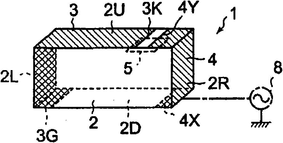
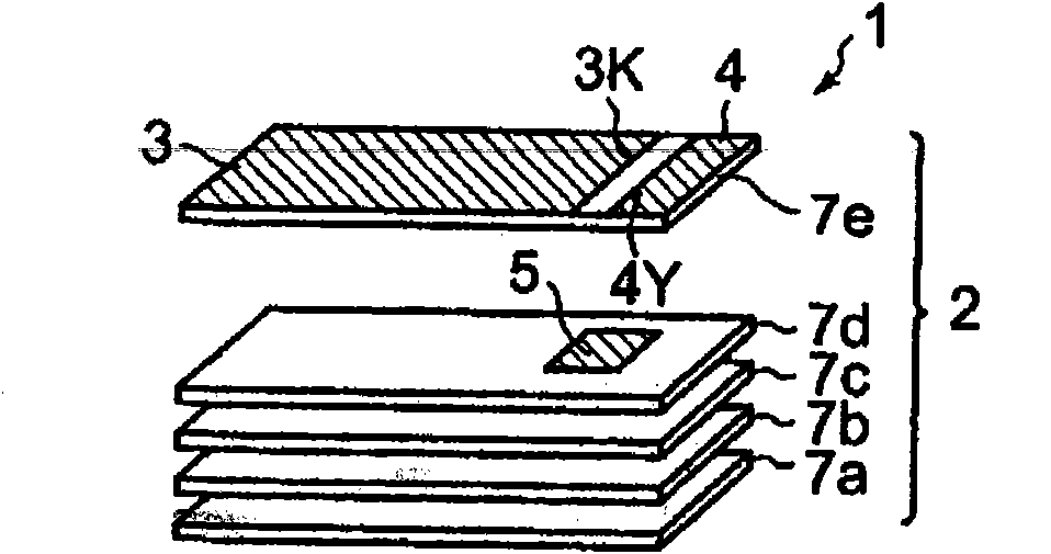
[0028] exist Figure 1a The capacitive feeding antenna according to the first embodiment of the present invention is shown by a schematic perspective view in FIG. Figure 1b show Figure 1a Schematic exploded view of a capacitively powered antenna. The capacitive feeding antenna 1 of the first embodiment has a dielectric substrate 2 as a substrate, a radiation electrode 3 , a feeding electrode 4 and a floating electrode 5 . The dielectric substrate 2 is configured in a rectangular parallelepiped shape, and the dielectric substrate 2 is configured so that a plurality of (in Figure 1b In the example, five layers) the insulating layers 7a to 7e are laminated and integrated. The radiation electrode 3 is formed on the upper surface (in other words, the upper surface of the uppermost layer 7 e ) 2U from the bottom surface 2D of the dielectric substrate 2 via the side sur...


PUM


Abstract

In a dielectric substrate (2) on which a radiation electrode (3) and a feeding electrode (4) are formed, a plurality of insulating layers (7a-7e) are laminated integrally. On the surface of the same insulating layer of the dielectric substrate (2), the open end (3K) of the radiation electrode (3) and the capacity coupling end (4Y) of the feeding electrode (4) are formed. On the surface of the insulating layer where the open end (3K) of the radiation electrode (3) and the capacity coupling end (4Y) of the feeding electrode (4) are not formed, a floating electrode (5) is formed. The floating electrode (5) is formed commonly to the open end (3K) of the radiation electrode (3) and the capacity coupling end (4Y) of the feeding electrode (4) such that a capacity is formed between the open end (3K) of the radiation electrode (3) and the capacity coupling end (4Y) of the feeding electrode (4) oppositely to the laminating direction of the insulating layers (7a-7e).

Description

technical field [0001] The present invention relates to a capacitive feeding antenna having a capacitive feeding type radiation electrode and a wireless communication device having the capacitive feeding antenna. Background technique [0002] exist Figure 5 An example of a capacitive feeding antenna is shown in a schematic perspective view (for example, refer to Patent Document 1). This capacitive feeding antenna 30 is configured to include a dielectric substrate 31 , a radiation electrode 32 , a feeding electrode 33 , and a ground electrode 34 . In this capacitive feeding antenna 30 , the dielectric substrate 31 is formed in a rectangular parallelepiped shape. Radiation electrode 32 from the above-mentioned dielectric substrate 31 Figure 5 The lower end of the shown right end surface 31R is extended to the upper side, and also spreads over the upper surface 31U of the dielectric substrate 31, and is extended halfway from the right end edge to the left end edge of the upp...

Claims


Application Information

Patent Timeline
Patent Type & Authority Applications(China)
IPC IPC(8): H01Q1/38H01Q9/40
CPCH01Q9/0457H01Q7/00H01Q1/2283H01Q9/42H01Q9/40H01Q11/08
Inventor 田村诚道平野悟栉比裕一
Owner MURATA MFG CO LTD
Why Eureka
Try Eureka