
Intelligent power supply method and intelligent power supply system for wireless mouse

A wireless mouse and wireless power supply technology, applied in the mouse field, can solve the problems of power dissipation, limited wireless power supply area and wireless mouse use space range, non-compliance, etc., to expand the use distance and range, the mouse operation is flexible and reliable, compact effect

Inactive Publication Date: 2010-10-06
CHONGQING JIAOTONG UNIVERSITY
View PDF0 Cites 11 Cited by
  • Summary
  • Abstract
  • Description
  • Claims
  • Application Information

AI Technical Summary

Problems solved by technology

[0002] At present, the wireless mouse is a better way to solve the problem of excessive computer wiring and the use of the mouse is affected by the length of the mouse cable. Most wireless mice use batteries as power sources. After a period of use, the batteries need to be replaced, which is not only inconvenient to use, but also economical. and environmental issues
[0003] Public reports in the prior art use wireless power supply to solve this problem, but most of them use transformer coupling to realize the transmission of electric energy. This method requires a transmission pad, and the mouse cannot leave the energy transmission pad, otherwise it cannot work. In addition, the power supply method is a continuous power supply method, which will dissipate a large amount of power, which does not meet the requirements of today's low-carbon life
[0004] There are also some published patent technologies that use magnetic coupling resonance wireless power supply technology to achieve power supply. This method not only requires the coupling coil to have a certain direction, but also requires the resonant coil to have a certain volume, which also limits the wireless power supply area and the wireless mouse. Use space range
At the same time, continuous power supply will also bring the disadvantages of excessive electromagnetic radiation and excessive energy consumption.

Method used


Image

  • Intelligent power supply method and intelligent power supply system for wireless mouse
  • Intelligent power supply method and intelligent power supply system for wireless mouse
  • Intelligent power supply method and intelligent power supply system for wireless mouse

Examples


Embodiment Construction

[0030] Hereinafter, preferred embodiments of the present invention will be described in detail with reference to the accompanying drawings. It should be understood that the preferred embodiments are only for illustrating the present invention, but not for limiting the protection scope of the present invention.

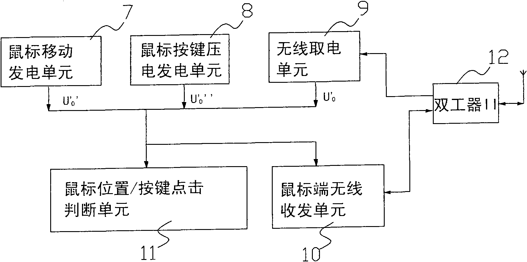
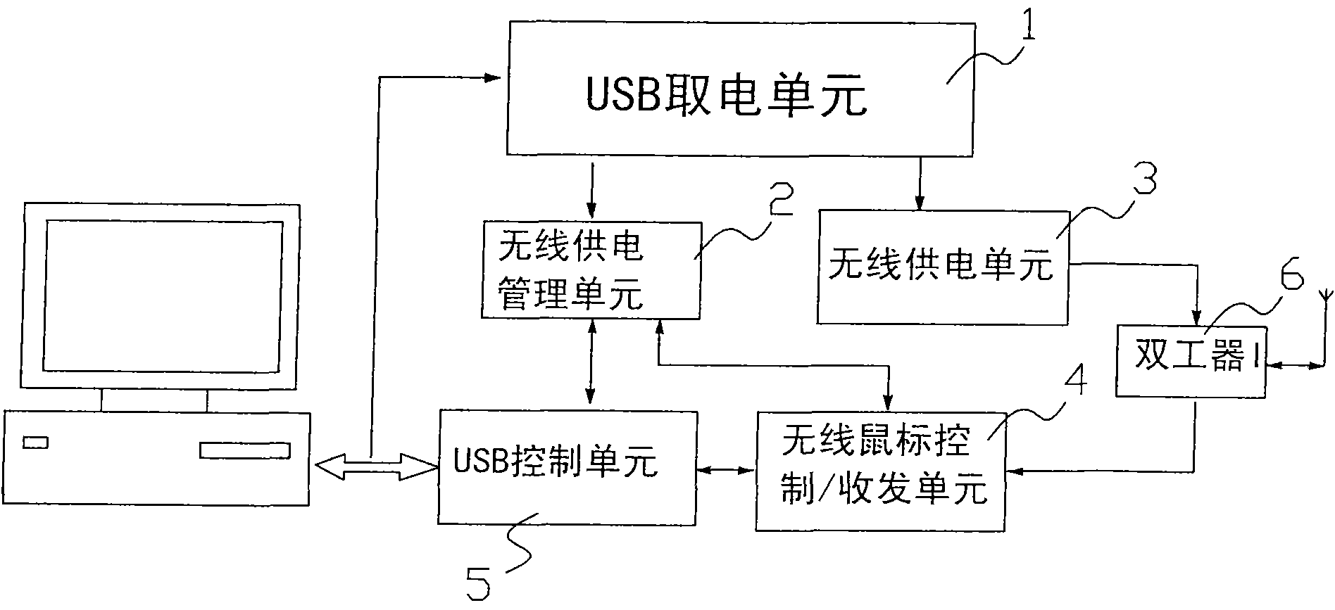
[0031] The intelligent wireless power supply method of the wireless mouse of the present invention is completed by using the host device connected to the USB interface of the computer and the mouse device arranged on the mouse body through wireless communication, and the working voltage of each working unit of the host device is taken as From the USB bus, the method includes a host-side device control strategy and a mouse-side device control strategy:

[0032] Among them, the host device control strategy includes:

[0033] The wireless power supply management unit monitors whether the use request signal of the wireless mouse is received in real time through the wirele...


PUM


Abstract

The invention discloses an intelligent power supply method for a wireless mouse. A host which is connected with a USB interface of a computer, and a mouse unit which is mounted in the mouse are utilized through a wireless communication mode in the method; working voltage of each working unit of the host is from a USB bus; and the method comprises a host control strategy and a mouse unit control strategy: the design thinking is that power is merely supplied to the mouse in operation while the power is shut down when the mouse is in servo status, the time slot of a user is recorded, a neural network software is used for forecasting time span threshold value of next servo, and thus no power is supplied to the mouse not in operation, thereby greatly saving power and meeting low-carbon living requirement. The invention also discloses an intelligent power supply system for the wireless mouse. The system has the advantages of compact structure and easy operation.

Description

technical field [0001] The invention relates to the technical field of a mouse, in particular to an intelligent power supply method for a wireless mouse, and also relates to an intelligent power supply system for a wireless mouse. Background technique [0002] At present, the wireless mouse is a better way to solve the problem of excessive computer wiring and the use of the mouse is affected by the length of the mouse cable. Most wireless mice use batteries as power sources. After a period of use, the batteries need to be replaced, which is not only inconvenient to use, but also economical. and environmental issues. [0003] Public reports in the prior art use wireless power supply to solve this problem, but most of them use transformer coupling to realize the transmission of electric energy. This method requires a transmission pad, and the mouse cannot leave the energy transmission pad, otherwise it cannot work. In addition, the power supply method is a continuous power su...

Claims


Application Information

Patent Timeline
IPC IPC(8): G06F1/26
CPCY02B60/50
Inventor 张奔牛郑博仁
Owner CHONGQING JIAOTONG UNIVERSITY
Learn More