
Disc brake apparatus

A disc brake and equipment technology, applied in the direction of mechanical equipment, brake type, axial brake, etc., can solve the problems of uneven wear of the liner, insufficient surface pressure distribution, etc., to reduce processing costs, stable performance, Effect of suppressing brake noise

Active Publication Date: 2010-10-06
ADVICS CO LTD
View PDF5 Cites 9 Cited by
  • Summary
  • Abstract
  • Description
  • Claims
  • Application Information

AI Technical Summary

Problems solved by technology

Therefore, the surface pressure distribution of the liner relative to the disc rotor is insufficient, and uneven wear of the liner along the rotor circumference is inevitable

Method used


Image

  • Disc brake apparatus
  • Disc brake apparatus
  • Disc brake apparatus

Examples


no. 1 approach

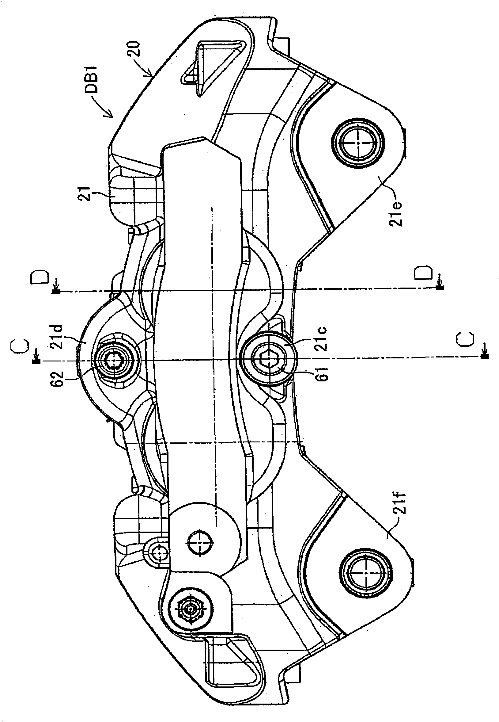
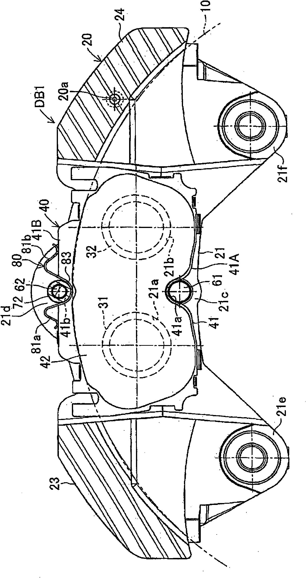
[0023] Figure 1 to Figure 6 A first embodiment is shown in which the disc brake device of the present invention is used as an opposed-piston type (fixed type) disc brake device for a vehicle. The disc brake apparatus DB1 according to the first embodiment is provided with a disc rotor 10 connected to a hub (rotation member not shown in the figure) and integrally with a wheel (not shown) Rotation; brake caliper 20, which is arranged to straddle a part of the outer circumference of the disc rotor 10; four pistons 31, 32, 33, 34 connected to the brake caliper 20; inner brake pads 40; and the outer brake pad 50. The disc brake apparatus DB1 is also provided with an inner inner peripheral support shaft 61 , an inner outer peripheral support shaft 62 , an outer inner peripheral support shaft 71 , an outer outer peripheral support shaft 72 , and a leaf spring 80 in the caliper 20 .

[0024] Such as Figure 5 As shown, the disc rotor 10 has circular braking surfaces 10 a , 10 b cla...

no. 2 approach

[0046] Figure 7 to Figure 10A second embodiment is shown in which the disc brake device of the present invention is used as an opposed-piston type (fixed type) disc brake device for a vehicle. The disc brake apparatus DB2 according to the second embodiment is provided with a disc rotor 110 connected to a hub (rotation member not shown in the figure) and integrally with a wheel (not shown) rotation; brake caliper 120, which is arranged to straddle a portion of the outer circumference of the disc rotor 110; four pistons 131, 132, 133, 134 connected to the brake caliper 120; inner brake pads 140; and the outer brake pad 150. The disc brake apparatus DB2 is also provided with an inner inner peripheral support shaft 161 , a pair of inner outer peripheral support shafts 162 , 162 , an outer inner peripheral support shaft 171 , a pair of outer outer peripheral support shafts 172 , 172 , and a leaf spring 180 .

[0047] According to the second embodiment, a pair of inner peripheral...


PUM


Abstract

The present invention is to stabilize behavior of brake pads at the time of braking of a disc brake so as to suppress generation of brake noise, and also to reduce the roll moment of the brake pads generated at the time of braking so as to suppress uneven abrasion of linings. A back plate (41) of a brake pad (40) is biased inward in the rotor radial direction by a plate spring (80). The back plate (41) is engaged at two points with an inner periphery support shaft (61) provided integrally with a caliper (20) on a V-shape inner peripheral abutment (41a) (provided in the back plate (41) on the inner side of a lining (42) in the rotor radial direction and on the center in the rotor circumferential direction), and engaged at one point with an outer periphery support shaft (62) provided integrally with the caliper (20) on an outer peripheral abutment (41b) (provided in the back plate (41) on the outer side of the lining (42) in the rotor radial direction and on the center in the rotor circumferential direction).

Description

technical field [0001] The present invention relates to a disc brake device, in particular to a disc brake device. The disc brake device is provided with: a disc rotor connected to a rotating member (such as a hub ) and rotate integrally with the rotating member; a brake caliper, which is connected to a supporting member (such as a vehicle body) so as to straddle a part of the outer circumference of the disc rotor; a pair of brake pads, the pair of brake pads pads arranged to clamp the disc rotor and supported on the caliper in a movable manner in the rotor axial direction through a support shaft; and a piston connected to the caliper for pressing the brake against the disc rotor A pad, the piston adapted to press the back plate of the brake pad such that the pad of the brake pad slidably presses against the braking surface of the disc rotor to brake the disc rotor. Background technique [0002] This type of disc brake apparatus is described, for example, in National Patent...

Claims


Application Information

Patent Timeline
Patent Type & Authority Applications(China)
IPC IPC(8): F16D55/224
CPCF16D55/228F16D2055/007F16D2121/02F16D65/0977F16D2055/0091F16D65/095
Inventor 森田慎一五明聪
Owner ADVICS CO LTD
Learn More