
Shaft deviator

A shaft reverser, axial motion technology, applied in the direction of gear transmission, belt/chain/gear, mechanical equipment, etc., can solve problems such as difficult driving, achieve the effect of convenient use, simple structure, and reduced technical requirements

Inactive Publication Date: 2011-12-28
姬保国
View PDF0 Cites 0 Cited by
  • Summary
  • Abstract
  • Description
  • Claims
  • Application Information

AI Technical Summary

Problems solved by technology

[0004] The object of the present invention is to provide a shaft reversing device, the input shaft of which can rotate in the same direction as the output shaft, and can also rotate in the opposite direction, so as to solve the problem that the connecting body of the tractor and the trailer must be reversed when it is reversed from the general reverse technology. Difficulty driving due to driving skills

Method used


Image

  • Shaft deviator
  • Shaft deviator
  • Shaft deviator

Examples


Embodiment Construction

[0019] The content of the present invention will be further described below in conjunction with the accompanying drawings and embodiments.

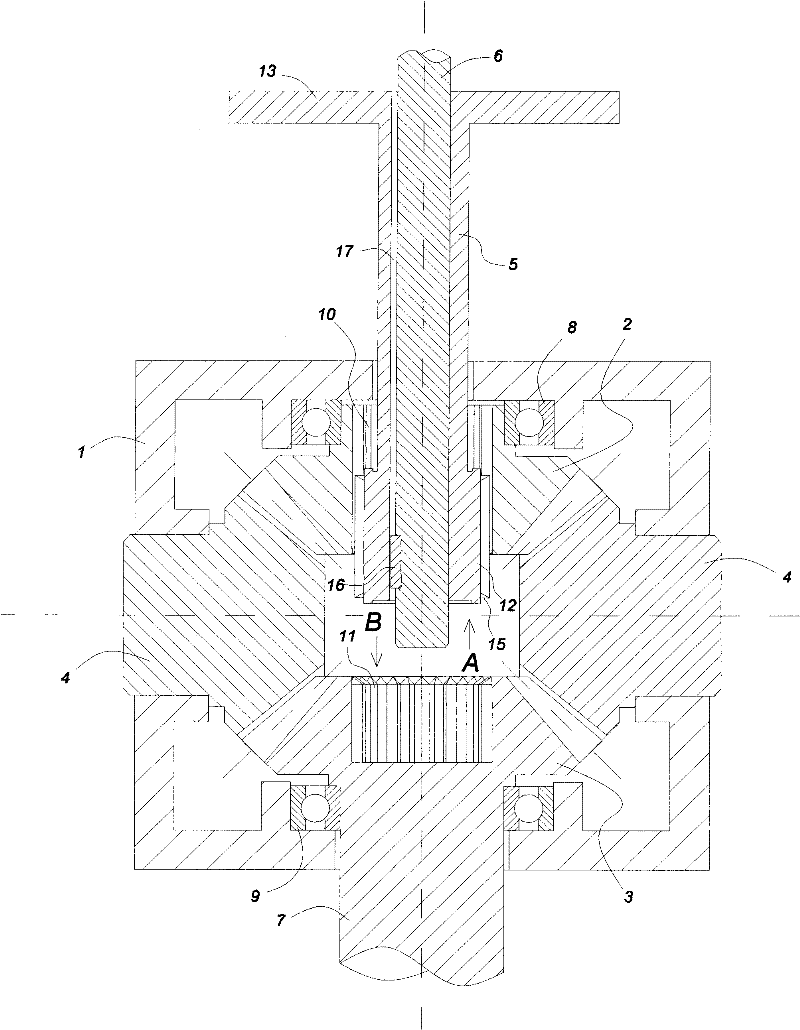
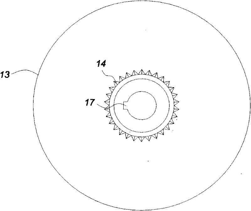
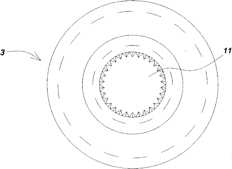
[0020] Such as figure 1 As shown, the shaft commutator consists of a case 1, a first bevel gear 2, a second bevel gear 3, a transmission bevel gear 4, a reversing shaft 5, an input shaft 6 and an output shaft 7, and also includes a first bearing 8 and Second bearing 9. There are two transmission bevel gears 4 in this embodiment, and the output shaft 7 is integrally connected with the second bevel gear 3 .

[0021] Among them, the first bevel gear 2 is installed in the box body 1 through the first bearing 8; the second bevel gear 3 is installed in the box body 1 through the second bearing 9; the transmission bevel gear 4 is installed in the box body 1 through the shaft hole on the box body 1 Inside the box 1. The first bevel gear 2 , the second bevel gear 3 and the transmission bevel gear 4 can all rotate relative to the casing 1 . The...


PUM


Abstract

The invention provides a shaft deviator. In the shaft deviator, an input shaft can be in homodromous rotation and in reversing rotation with an output shaft. The shaft deviator comprises a box body, a first bevel gear, a second bevel gear, a drive bevel gear, a reversing shaft and the input shaft, wherein the first bevel gear, the second bevel gear and the drive bevel gear can be rotated relativeto the box body; the second bevel gear is extended out of the box body to be connected with the output shaft; the first bevel gear is opposite to the second bevel gear; the first bevel gear is in transmission with the second bevel gear through the drive bevel gear; a first keyhole is formed on the first bevel gear; a second keyhole is formed on the second bevel gear; the reversing shaft passes through the first bevel gear; the input shaft is arranged in the reversing shaft; a bond axis part which can be matched with the first keyhole and the second keyhole respectively is arranged at one end in the box body of the reversing shaft; and a lifting and pulling part used for driving the reversing shaft to do axial motion is arranged at one end of the reversing shaft outside the box body. The shaft deviator can solve the problem that because a driving technique opposite to the other back-off technique must be adopted when a connecting body of a tractor and a trailer backs off, the connecting body is difficult to drive.

Description

technical field [0001] The invention relates to a steering gear for changing the rotation direction of an input shaft. Background technique [0002] According to known driving techniques, when the car is reversing, if you turn the steering wheel to the left, the rear of the car will swing to the left; if you turn the steering wheel to the right, the rear of the car will swing to the right. car. However, once the tractor is connected to the trailer, the connecting body of the tractor and the trailer is in the process of reversing. Swing to the right; turn the steering wheel to the right on the tractor, and the rear of the trailer will swing to the left. [0003] It is precisely because the driving technique of the connecting body of the tractor and the trailer when reversing must be opposite to the driving technique of ordinary cars when reversing, so that the driver has to use reverse thinking to drive when reversing, so the driver's driving reaction at this time is usuall...

Claims


Application Information

Patent Timeline
Patent Type & Authority Patents(China)
IPC IPC(8): F16H3/14
Inventor 姬保国
Owner 姬保国
Learn More