
Focusing device in long-focus and heavy-caliber optical system

An optical system and large-aperture technology, applied in the direction of optics, optical components, installation, etc., can solve the problems of large focusing error, difficult installation and adjustment, and difficulty in determining the coaxial precision, etc., to achieve easy installation and adjustment, simple structure, and adjustment The effect of high focus precision

Inactive Publication Date: 2010-09-22
CHANGCHUN INST OF OPTICS FINE MECHANICS & PHYSICS CHINESE ACAD OF SCI
View PDF3 Cites 2 Cited by
  • Summary
  • Abstract
  • Description
  • Claims
  • Application Information

AI Technical Summary

Problems solved by technology

[0003] In order to solve the problems that the existing focusing mechanism is difficult to determine the coaxial accuracy of the optical axis of other fixed mirror groups during installation, the installation and adjustment is difficult, and the focusing error is large, the present invention provides a long focal length, large aperture optical system. focusing device

Method used


Image

  • Focusing device in long-focus and heavy-caliber optical system
  • Focusing device in long-focus and heavy-caliber optical system
  • Focusing device in long-focus and heavy-caliber optical system

Examples


specific Embodiment approach 1

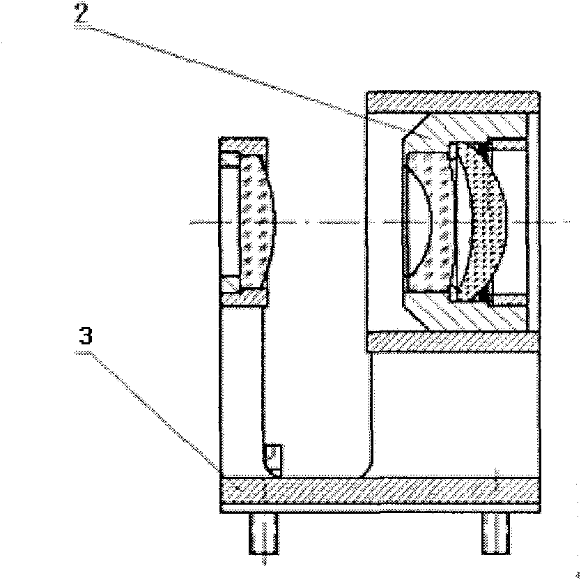
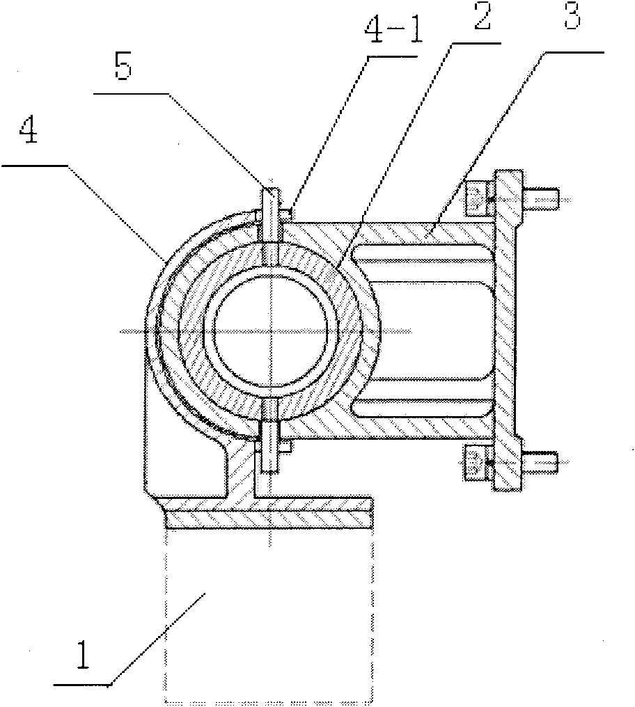
[0014] Specific implementation mode 1: Combination Figure 2 to Figure 6 In this embodiment, the focusing device in the long focal length and large aperture optical system includes an electronically controlled displacement platform 1 and a focusing lens group 2, and it also includes a slide rail seat 3, a shift fork 4 and two cylinders 5. The focus lens group 2 is arranged in the slide rail seat 3, the shift fork 4 is provided outside the slide rail seat 3, and the shift fork 4 is fixedly connected to the electronically controlled displacement platform 1; the focus lens group 2 and the two cylinders 5 adopt The two ends of the shift fork 4 are respectively provided with U-shaped grooves 4-1, and the slide rail seat 3 is provided with two long slot holes 3-1, and the cylinder 5 passes through the long grooves on the slide rail seat 3 in turn The hole 3-1 and the U-shaped groove 4-1 on the shift fork 4.

[0015] The accuracy of the electronically controlled displacement platform 1...


PUM


Abstract

The invention discloses a focusing device in a long-focus and heavy-caliber optical system, relating to the technical field of optical machinery and aiming to solve the problems that the traditional focusing mechanism is difficult to determine the coaxial precision with optical axes of other fixed mirror groups during installation and has high difficulty in installation and adjustment. The device comprises an electric control displacement platform, a focusing mirror group, a sliding rail seat, a shifting fork and two cylinders, wherein the focusing mirror group is arranged in the sliding rail seat; the shifting fork is arranged on the outer side of the sliding rail seat and is fixedly connected with the electric control displacement platform; the focusing mirror group is in threaded connection with the two cylinders; U-shaped grooves are respectively arranged at two ends of the shifting fork; the sliding rail seat is provided with two slotted holes; and the cylinders sequentially pass through the slotted holes of the sliding rail seat and the U-shaped grooves of the shifting fork. The invention is widely applied to the optical system.

Description

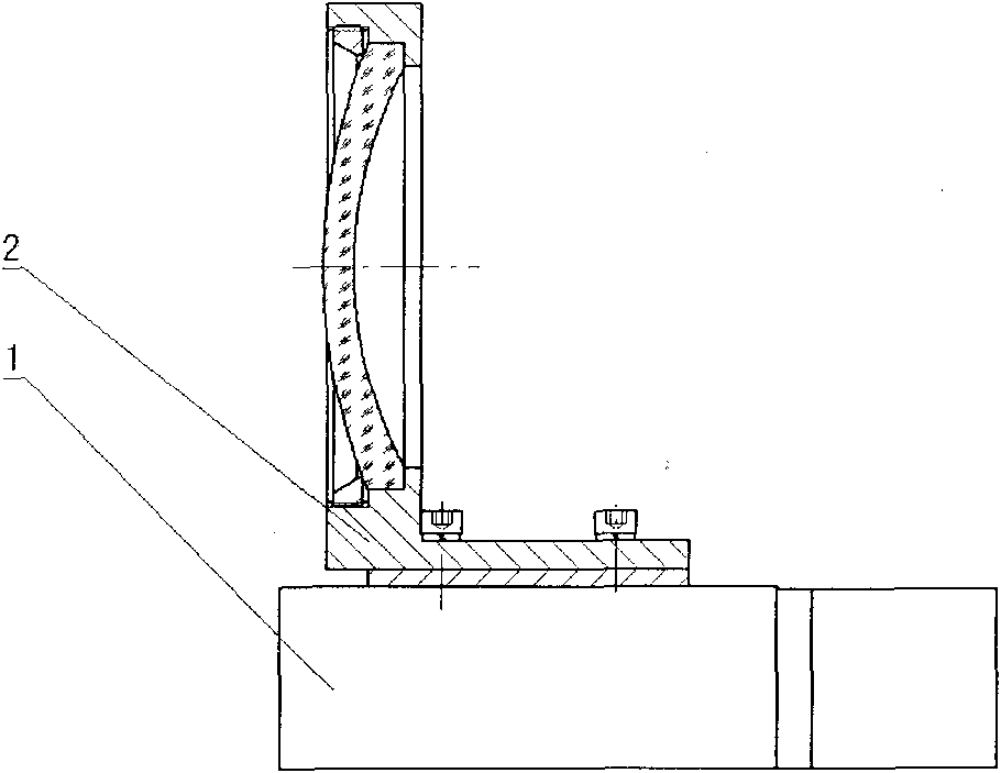
Technical field [0001] The present invention relates to the technical field of optical machinery, in particular to a focusing device in an optical system. Background technique [0002] At present, the application environment of long focal length and large-aperture optical systems is often harsh, and the environment has many influences on the optical system. For example: changes in ambient temperature, changes in atmospheric pressure, system vibration, and external shocks will cause the focal plane of the optical system to have a certain degree of axial offset, which will adversely affect the imaging quality of the system. The existing focusing mechanism is composed of figure 1 As shown, the focusing mechanism is mainly composed of a focusing lens group and a high-precision electronically controlled mobile platform. The disadvantage of this structure is that it is difficult to ensure the coaxial accuracy of the focusing mechanism and the optical axis of other fixed lens groups dur...

Claims


Application Information

Patent Timeline
Patent Type & Authority Applications(China)
IPC IPC(8): G02B7/04
Inventor 邵帅曹立华
Owner CHANGCHUN INST OF OPTICS FINE MECHANICS & PHYSICS CHINESE ACAD OF SCI
Learn More