
Captive ball quick-release joint structure

A joint structure and tethered ball technology, applied in cable joints, fiber mechanical structures, etc., can solve the problems of high production cost, difficult maintenance, and optical cables are easily twisted, and achieve the effect of simple structure and low manufacturing cost.

Active Publication Date: 2013-03-20
SHENZHEN ANTUOSHAN TECH
View PDF0 Cites 0 Cited by
  • Summary
  • Abstract
  • Description
  • Claims
  • Application Information

AI Technical Summary

Problems solved by technology

[0002] At present, most of the tethered ball quick-release joint structures are used alone for the transfer connection of the cable to transmit electrical signals to the aerial tethered ball task equipment, and some also transmit the photoelectric signal for the transfer connection, in order to protect the optical cable from torsional deformation (from the tethered The optical cable from the task equipment on the ball to the quick release joint, when the tethered ball rotates under the action of wind, if no measures are taken, the optical cable is easy to be twisted), this structure is used in many countries. Backflow ring or photoelectric composite backflow ring, so this kind of quick release joint has complex structure and high production cost, and it is easy to cause shutdown due to the failure of the photoelectric backflow ring. At the same time, it is difficult to maintain. The mooring ball must be recovered to the ground to carry out maintenance work.

Method used


Image

  • Captive ball quick-release joint structure
  • Captive ball quick-release joint structure
  • Captive ball quick-release joint structure

Examples


Embodiment Construction

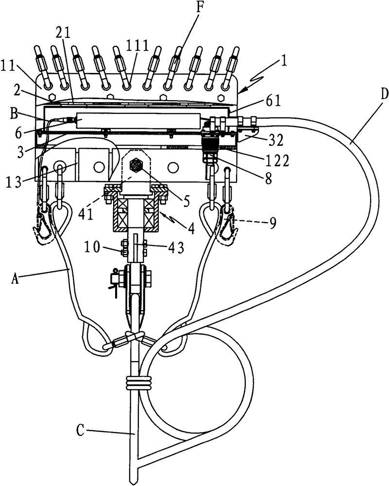
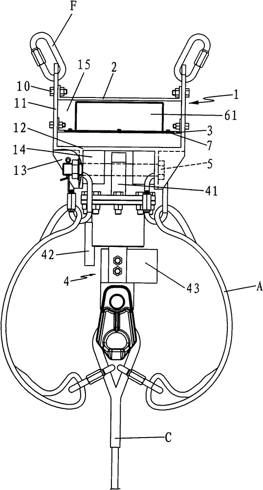
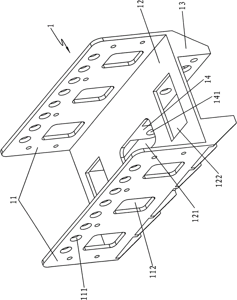
[0039] like Figure 1 to Figure 2 As shown, the present invention mainly includes a quick-release joint steel structure frame 1, a fixing plate 2, an installation plate 3, and an adapter 4, wherein the fixing plate 2 and the installation plate 3 are connected to the quick-release joint steel structure frame by bolts 10 1 On the side plate 11 of the upper half, the height difference between the two plates forms an accommodating space 15; an optical fiber end box 6 is arranged in the accommodating space 15, and an optical fiber plug and connector are arranged on the optical fiber end box 6 Line B, the optical fiber optical end box 6 is provided with a waterproof cover 61, the waterproof cover 61 is fixed on the mounting plate 3 by bolts 10, and is waterproofed with a rubber gasket 7; A support plate 14 is provided, and the support plate 14 is connected with the connection plate 41 of the adapter 4 through the cotter pin 5. The adapter 4 is provided with a bearing seat limit plat...


PUM


Abstract

The invention discloses a captive ball quick-release joint structure. The structure mainly comprises a quick-release joint steel structural frame, a retaining plate, a mounting plate and an adapter, wherein the quick-release joint steel structural frame is provided with a bottom plate, a side plate and a reinforcing rib; the retaining plate and the mounting plate are connected to the side plate of the upper half part of the quick-release joint steel structural frame; an accommodating space is formed between the retaining plate and the mounting plate ; the reinforcing rib is provided with a supporting plate; and the adapter is connected with the supporting plate through a split pin. By connecting an optical cable with a captive ball from an anchoring hoist, the structure transmits an optical signal and an electric signal to a mission cabin; and the structure is provided with the adapter, so 360-degree rotation is realized and the torque force of the optical cable is released; and therefore, the structure has a connection function, a simple structure and high safety and also has the function that the optical cable can be prevented from being influenced by the torque force.

Description

technical field [0001] The invention relates to a quick-release joint structure, in particular to a tethered ball quick-release joint structure for air-tethered ball optical fiber connection, cable connection and cable connection. Background technique [0002] At present, most of the tethered ball quick-release joint structures are used alone for the transfer connection of the cable to transmit electrical signals to the aerial tethered ball task equipment, and some also transmit the photoelectric signal for the transfer connection, in order to protect the optical cable from torsional deformation (from the tethered The optical cable from the task equipment on the ball to the quick release joint, when the tethered ball rotates under the action of wind, if no measures are taken, the optical cable is easy to be twisted), this structure is used in many countries. Backflow ring or photoelectric composite backflow ring, so this kind of quick-release joint has a complex structure an...

Claims


Application Information

Patent Timeline
Patent Type & Authority Patents(China)
IPC IPC(8): G02B6/44H02G15/08
Inventor 梁锡武
Owner SHENZHEN ANTUOSHAN TECH
Learn More