Double-air-source air path automatic switching pressurizer

A technology of automatic switching and pressure maintaining devices, applied in gas/liquid distribution and storage, piping systems, mechanical equipment, etc.

Active Publication Date: 2010-09-22
EGING PHOTOVOLTAIC TECHNOLOGY CO LTD
View PDF9 Cites 5 Cited by
  • Summary
  • Abstract
  • Description
  • Claims
  • Application Information

AI Technical Summary

Problems solved by technology

[0003] In order to solve the problems caused by the single gas path and the existing dual gas path in production, the present invention provides a dual gas source gas path automatic conversion pressure maintaining device

Method used


Image

  • Double-air-source air path automatic switching pressurizer
  • Double-air-source air path automatic switching pressurizer

Examples


Embodiment Construction

[0011] The specific embodiments of the present invention will be described in detail below with reference to the accompanying drawings.

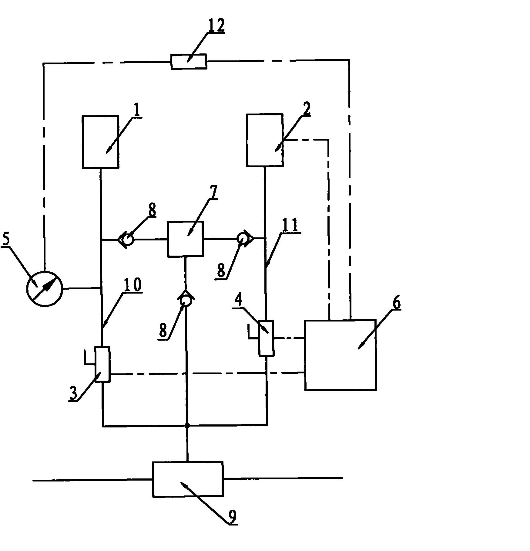
[0012] The dual air source gas circuit automatic conversion pressure maintaining device, such as figure 1 As shown, it consists of a main air pump 1, an auxiliary air pump 2, a main solenoid valve 3, an auxiliary solenoid valve 4, a pressure gauge 5, an electric controller 6, a supplementary pressure air bag 7, a one-way valve 8, a pneumatic valve 9, and a main airway 10. The main air pump 1 is connected with the pneumatic valve 9 through the main air passage 10 and the main solenoid valve 3; the auxiliary air pump 2 is connected with the pneumatic valve 9 through the auxiliary air passage 11 and the auxiliary solenoid valve 4. The main air pump 1 , The auxiliary air pump 2 is connected with the supplementary air bag 7 through the one-way valve 8, the pressure gauge 5 is installed on the main air passage 10, the main solenoid valve 3 and the...


PUM


Abstract

The invention relates to a double-air-source air path automatic switching pressurizer, which comprises a main air pump, an auxiliary air pump, a main electromagnetic valve, an auxiliary electromagnetic valve, a pressure gauge, an electric controller, a pressure compensation air bag, a non-return valve, a pneumatic valve, a main air duct, an auxiliary air duct and a pressure sensor, wherein the main air pump is communicated with the pneumatic valve through the main air duct and the main electromagnetic valve; the auxiliary air pump is communicated with the pneumatic valve through the auxiliary air duct and the auxiliary electromagnetic valve; both the main air pump and the auxiliary air pump are connected with the pressure compensation air bag through the non-return valve; the pressure gauge is installed on the main air duct; the main electromagnetic valve and the auxiliary electromagnetic valve are controlled by the electric controller; and the pressure gauge is connected with the electric controller through the pressure sensor. When the main air pump breaks down, the pressurizer can automatically switch into the auxiliary air pump to supply air, and can ensure air supply under stable pressure, thereby ensuring normal work of the pneumatic valve.

Description

Technical field: [0001] The invention relates to a gas path conversion device, in particular to a dual air source gas path automatic conversion pressure maintaining device. Background technique: [0002] Pneumatic valves are more and more used in various industrial equipment. The work of pneumatic valves is controlled by high-pressure air or high-pressure nitrogen. In order to reduce costs, manufacturers generally use high-pressure air to control pneumatic valves, and air compressors generate high-pressure air to supply equipment. Use, most manufacturers now use a single air supply, once the air compressor fails, the high-pressure air source will disappear, the pneumatic valve will not work properly, affecting the operation of the production equipment, for example, in the production process of solar cells , Many production equipment needs water, such as cleaning equipment and cooling equipment in the production process of solar cells, the control of water supply pipelines is...

Claims


Application Information

Patent Timeline
IPC IPC(8): F17D3/01F17D1/04F17D5/00
Inventor 王瑞勋
Owner EGING PHOTOVOLTAIC TECHNOLOGY CO LTD
Why Eureka
Try Eureka