


Quick Research
Generate reliable direction feasibility study reports for your R&D in just a few steps.

Technical Q&A
Discover and master advanced knowledge NOW. Basics, ideas, possibilities, all at once.

Find Solutions
As an expert in R&D theories, this can generate solutions to your technical problems instantly.

Evaluate Feasibility
Analyze your overall solution with one click, know your potential R&D risks in advance.

Monitor Landscape
Get weekly tech updates, stay abreast of the latest tech innovations and key insights.
Charging system for electric vehicle
A technology of electric vehicles and charging systems, applied in the direction of electric vehicle charging technology, electric vehicles, charging stations, etc., can solve the problems of increasing power generation, huge costs, etc., and achieve the effect of effective use of electric energy
- Summary
- Abstract
- Description
- Claims
- Application Information
AI Technical Summary
Problems solved by technology
Method used
Image

Examples
Embodiment Construction
[0021] Hereinafter, ideal embodiments of the present invention will be described in detail with reference to the accompanying drawings in order to facilitate those skilled in the art to implement the technical idea of the present invention.
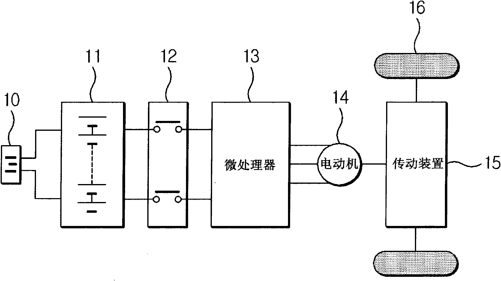
[0022] figure 1 It is a block diagram showing the interior of an electric vehicle.
[0023] Such as figure 1 As shown, an electric vehicle includes a charging terminal 10 , a vehicle battery 11 , a power relay assembly (Power Relay Assembly) 12 , a microprocessor 13 for motor control, a motor 14 , a transmission 15 , and tires 16 . The charging terminal 10 is a terminal for the vehicle to receive electric energy. Electric energy input through the charging terminal 10 is stored in the vehicle battery 11 . The electric energy supplied from the vehicle battery 11 is input to the microprocessor 13 through the power relay group 12, and the microprocessor 13 uses the input electric energy to control the electric motor 14 to the required to...
PUM
 Abstract
Description
Claims
Application Information
 - R&D Engineer
- R&D Manager
- IP Professional
- Industry Leading Data Capabilities
- Powerful AI technology
- Patent DNA Extraction
Browse by: Latest US Patents, China's latest patents, Technical Efficacy Thesaurus, Application Domain, Technology Topic, Popular Technical Reports.
© 2024 PatSnap. All rights reserved.Legal|Privacy policy|Modern Slavery Act Transparency Statement|Sitemap|About US| Contact US: help@patsnap.com