
Connection structure of engine exhaust gas reclrculation pipe and plastic intake manifold

A technology of exhaust gas recirculation and intake manifold, which is applied in the direction of exhaust gas recirculation, engine components, combustion engines, etc., and can solve the problems of low reliability and melting of plastic intake manifolds

Active Publication Date: 2010-09-15
CHONGQING CHANGAN AUTOMOBILE CO LTD
View PDF4 Cites 14 Cited by
  • Summary
  • Abstract
  • Description
  • Claims
  • Application Information

AI Technical Summary

Problems solved by technology

[0003] The invention proposes an improved connection structure between the engine exhaust gas recirculation pipe and the plastic intake manifold. The purpose is to solve the ablation and melting of the plastic intake manifold by the high-temperature gas in the engine EGR system. low sex problem

Method used


Image

  • Connection structure of engine exhaust gas reclrculation pipe and plastic intake manifold
  • Connection structure of engine exhaust gas reclrculation pipe and plastic intake manifold
  • Connection structure of engine exhaust gas reclrculation pipe and plastic intake manifold

Examples


Embodiment Construction

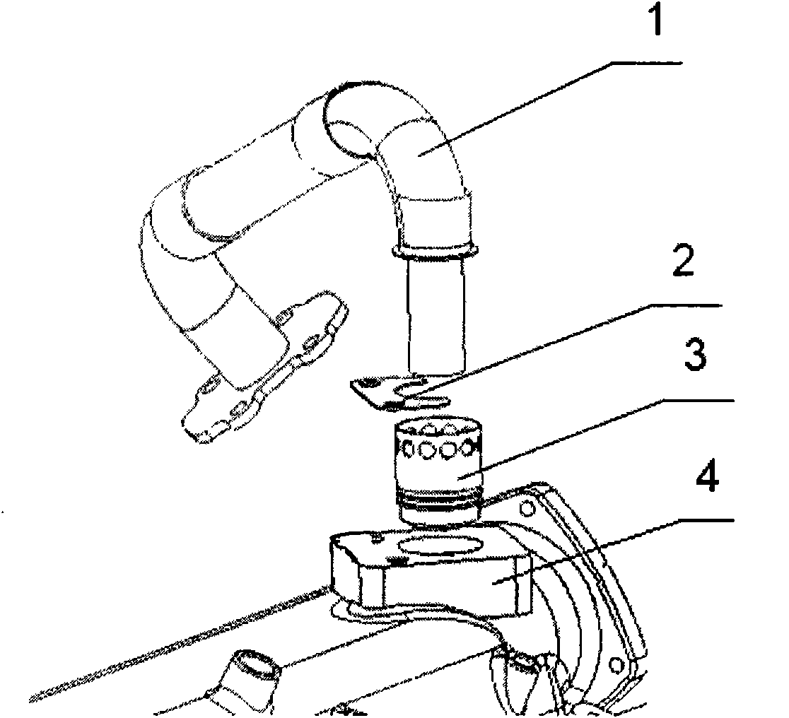
[0016] The connection structure is described in detail below in conjunction with the accompanying drawings:

[0017] see figure 1 and figure 2 , the connection structure includes the exhaust gas recirculation inlet pipe 1 and the plastic intake manifold 4, and a connecting boss is arranged at the entrance where the plastic inlet manifold 4 is connected to the exhaust gas recirculation inlet pipe 1, and there is a connecting boss on the boss Bolt hole.

[0018] A thermal insulation sleeve 3 is arranged between the connection part of the exhaust gas recirculation inlet pipe 1 and the plastic intake manifold 4, the material of the thermal insulation sleeve is stainless steel, and the wall thickness is not less than 2mm. The heat insulation sleeve 3 is installed in the inlet of the installation boss of the plastic intake manifold 4, and the connection head of the exhaust gas recirculation inlet pipe 1 is inserted into the heat insulation sleeve 3, and the two are connected thro...


PUM

PropertyMeasurementUnit
widthaaaaaaaaaa

Abstract

The invention discloses a connection structure of an engine exhaust gas reclrculation pipe and a plastic inlet manifold, comprising an exhaust gas recirculation inlet pipe and a plastic inlet manifold, a thermal sleeve pipe is arranged on the connection part of the exhaust gas recirculation inlet pipe and the plastic inlet manifold, the thermal sleeve pipe is arranged in an entrance of a connection lug boss of the plastic inlet manifold, a connecting head of the exhaust gas recirculation inlet pipe is inserted into the thermal sleeve pipe, and the exhaust gas recirculation inlet pipe and the plastic inlet manifold are connected and mutually separated by the thermal sleeve pipe. The connection structure can avoid the direct contact of the exhaust gas recirculation inlet pipe and the plastic inlet manifold, directly conducts high temperature to the plastic inlet manifold, reduces the wall surface temperature of the inlet manifold of the connection of the EGR (Exhaust Gas Recirculation) pipe and the plastic inlet manifold, better protects the inlet manifold, and improves the reliability of the plastic inlet manifold with the EGR system.

Description

technical field [0001] The invention relates to an engine exhaust gas recirculation system (Exhaust Gas Recirculation system). Background technique [0002] The exhaust gas recirculation system of the engine can effectively reduce the emission of the engine and the fuel consumption rate, and the exhaust gas recirculation (hereinafter referred to as EGR) technology is widely used in the engine. Since this technology is to reintroduce the high-temperature exhaust gas of the engine into the intake system, this leads to a high temperature on the wall surface of the intake manifold material at the connection between the exhaust gas recirculation pipe and the intake manifold. Generally, the allowable temperature of the aluminum alloy intake manifold is 250 degrees Celsius, and the allowable temperature of the plastic intake manifold is 130 degrees Celsius. Due to its advantages of low heat conduction, smooth wall and low density, plastic intake manifold has been widely used in th...

Claims


Application Information

Patent Timeline
Patent Type & Authority Applications(China)
IPC IPC(8): F02M25/07F02M35/104F02M26/12
CPCY02T10/121F02M35/10222F02M26/18F02M35/10321
Inventor 张小燕谯鑫蒲运平马为
Owner CHONGQING CHANGAN AUTOMOBILE CO LTD
Learn More