End cover set of brush direct current motor

A brush DC motor and end cap technology, applied in the direction of electric components, circuits, collectors, etc., to improve the bending angle, shorten the force arm, and solve the effect of buzzing

Active Publication Date: 2012-06-13
SHENZHEN TOPBAND CO LTD
View PDF0 Cites 0 Cited by
  • Summary
  • Abstract
  • Description
  • Claims
  • Application Information

AI Technical Summary

Problems solved by technology

[0006] The technical problem to be solved by the present invention is to provide a brushed DC motor that can simplify the installation of the metal brushes of the motor end cover group, and prevent the motor from losing speed and the brush blades from being easily deformed. Motor end cover set

Method used


Image

  • End cover set of brush direct current motor
  • End cover set of brush direct current motor
  • End cover set of brush direct current motor

Examples


Embodiment Construction

[0024] The preferred embodiments of the present invention will be described in detail below with reference to the drawings.

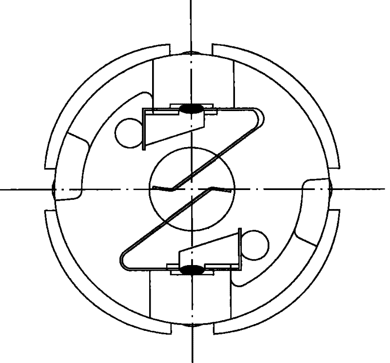
[0025] The overall structure of the brushed DC motor end cover group in the embodiment of the present invention is shown as follows Figure 4 As shown in , the rest of the structure of the motor is not shown in the figure. from Figure 4 It can be seen from the figure that the end cover group of the brushed DC motor is mainly composed of brushes 200 and a plastic cover 300 . The plastic cover is provided with a fixing position 301 and a wire end 302 . The fixing position 301 is used to fix the brush 200 . The wire end 301 is fixed with a wire, which is used to energize the brushes fixed on the plastic cover.

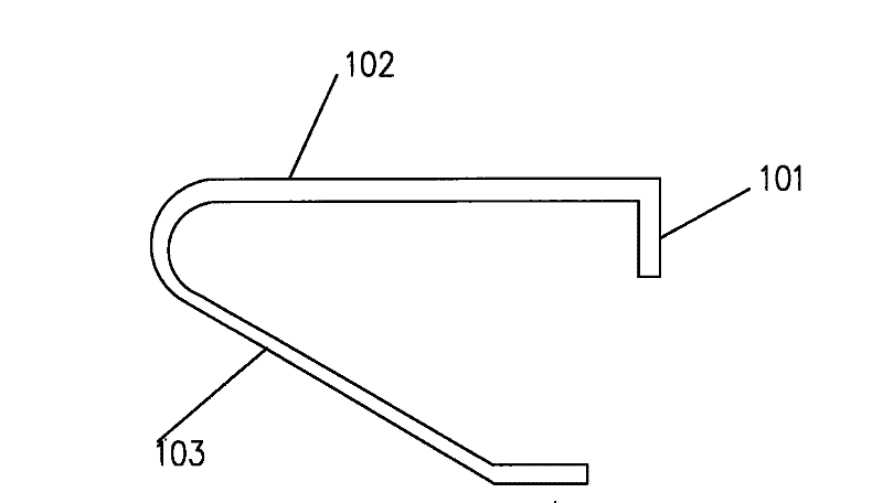
[0026] Figure 5 show Figure 4 The schematic diagram of the structure of the brush 200 in , which is formed by bending a strip of metal, includes a conductive part 201 , a force arm 202 and a brush part 203 . The conductive part 201 is used ...


PUM


Abstract

The invention relates to an end cover set of a brush direct current motor. The end cover set comprises an electric brush and a plastic cover, wherein the plastic cover is provided with a fixed position and a lead end; the electric brush comprises an electrically conductive part; the electrically conductive part is connected with the lead end and bends and extends inwards to form an acting force arm; the acting force arm is fixed at the fixed position and bends and extends inwards to form a brush sheet part. The end cover set is characterized in that: the end part of the brush sheet part bendsinwards; and the included angle between the broken line on the bending part and the extending central line of the brush sheet part is less than 90 degrees. The end cover set of the motor has the advantages of effectively overcoming the defects of the buzzing phenomenon, the speed reduction and the like generated by resonance of the electric brush, enhancing the irregular deformation force of the brush sheet part, making the installation of the metal brush and the phase exchange of the motor simpler and more convenient and effectively improving the performance difference of the positive and negative rotation of the motor by designing a lead installation point of the plastic cover and an installation structure of the electric brush according to the structure of the electric brush.

Description

technical field [0001] The invention relates to a direct current motor, in particular to an end cover group of a brushed direct current motor. Background technique [0002] At present, the end cover group of the domestic coreless brushed motor generally includes metal brushes and a plastic cover. The center point of the circular plastic cover. Two electric brushes are fixed on this fixing position, contact with the wire that is installed on the plastic cover. Among them, the structure of the brush Figure 1 like figure 1 As shown, its expanded structure diagram is shown as figure 2 As shown, the structural diagram of its installation on the plastic end cover is shown in Figure 3A , Figure 3B shown. It includes a conductive part 101 that is in contact with the wire. The conductive part is extended and bent to form a force arm 102 of the brush part. cover. The action force arm 102 is extended and bent to form the brush part 103 , and the bent part is marked as the ...

Claims


Application Information

Patent Timeline
Patent Type & Authority Patents(China)
IPC IPC(8): H02K5/22H01R39/24H02K13/00
Inventor 易明明
Owner SHENZHEN TOPBAND CO LTD
Why Eureka
Try Eureka