
Three-dimensional coordinate measuring system of handheld target trinocular camera

A measurement system and three-dimensional coordinate technology, applied in the direction of measuring devices, instruments, optical devices, etc., can solve the problems of reduced measurement accuracy, small effective field of view, and measurement failure, so as to improve the solution accuracy and avoid the reduction of edge measurement accuracy , the effect of improving reliability

Inactive Publication Date: 2010-09-01
GUILIN UNIV OF ELECTRONIC TECH
View PDF1 Cites 7 Cited by
  • Summary
  • Abstract
  • Description
  • Claims
  • Application Information

AI Technical Summary

Problems solved by technology

The effective field of view of the monocular visual coordinate measurement system is small, which cannot meet the requirements of a large measurement field of view and the reliability of the system is determined by a single camera. Although the binocular visual coordinate measurement system has expanded to the effective range, it is measured at the edge of the field of view The accuracy is reduced. At the same time, the binocular vision measurement system uses the parallax principle to solve the spatial coordinates. As long as one of the cameras cannot work normally, the measurement will fail

Method used


Image

  • Three-dimensional coordinate measuring system of handheld target trinocular camera
  • Three-dimensional coordinate measuring system of handheld target trinocular camera
  • Three-dimensional coordinate measuring system of handheld target trinocular camera

Examples


Embodiment 1

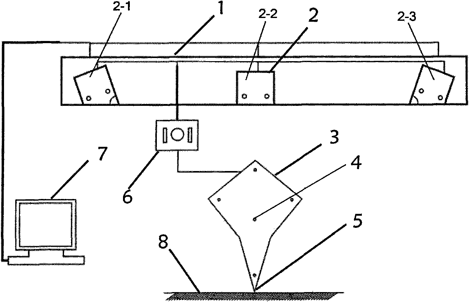
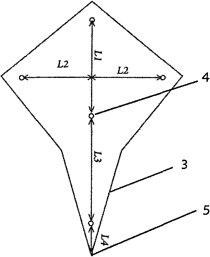
[0014] refer to figure 1 , 2 , 3, among the three cameras, the first camera 2-1, the second camera 2-2, and the third camera 2-3 are respectively placed in the camera card slot 2 of the camera array base 1, and the first camera 2 -1 and the third camera 2-3 are basically on the same plane, and the optical axis of the second camera 2-2 in the middle is at the angle between the optical axis of the first camera 2-1 and the third camera 2-3 On the bisected plane and perpendicular to the base 1 of the camera array, the angle β between the first camera 2-1, the third camera 2-3 and the base 1 of the camera array is 70 degrees, and the optical center of the first camera 2-1 reaches The second camera 2-2 optical center, the distance from the second camera 2-2 optical center to the third camera 2-3 optical center is L is 0.5 meters, and the hand-held target 3 is composed of 5 luminous marker points 4, Form a cross shape, the middle three luminous mark points 4 are on a straight line ...

Embodiment 2

[0016] The hand-held target 3 is composed of 9 luminous marking points 4, and its shape is rhombus. There are three luminous marking points 4 on each side of the rhombus, and there is one luminous marking point 4 in the middle. The distance is 25mm, the distances between the two diagonals are 60mm and 80mm respectively, and the distance between the light-emitting marker point at one end of the rhombus diagonal and the measurement contact point 5 is 20mm, and the rest are the same as in Example 1.

Embodiment 3

[0018] The hand-held target 3 is composed of 7 luminous marker points 4, which are in the shape of a cross, of which 5 luminous marker points 4 are on the same straight line with a distance of 30 mm. The distance between the measurement contact point 5 and the luminous marker point 4 at one end of the straight line is 20mm, and the other two luminous marker points 4 are on the same straight line as the second luminous marker point at the other end of the line, with a distance of 30mm, and the rest are the same as in embodiment 1.


PUM


Abstract

The invention provides a three-dimensional coordinate measuring system of a handheld target trinocular camera, which is characterized in that the camera are three in total; the camera is also provided with a handheld target and a camera array pedestal; three cameras are placed on the camera array pedestal; the cameras on the two sides are approximately placed in the same plane; the camera in the middle is placed in the dividing surface of the angle between optical axes of the two cameras; the handheld target is installed with illuminating index points in geometric figures; a frame synchronous triggering device controls the camera and collects handheld target images simultaneously; and three cameras form three binocular coordinate measuring systems. The three cameras of the measuring systems can establish three binocular coordinate measuring systems; in the public field of view of the three cameras, the solving precision of the three-dimensional coordinate measuring system can be improved through gravity algorithm; in unstable industrial environment, even if one camera can not work normally or can not collect pictures, the coordinate measuring system can still finish the measuring task, thus improving reliability of the system.

Description

technical field [0001] The invention relates to a three-dimensional coordinate measurement system, in particular to a three-dimensional coordinate measurement system for a hand-held target trinocular camera. Background technique [0002] The target-based three-dimensional coordinate measurement system collects the image of the handheld target through the camera, and solves the coordinates of the measured point through the computer. At present, the three-dimensional coordinate measurement system based on the handheld target mostly adopts a monocular or binocular camera structure. Professor Liu Shugui of Tianjin University uses a monocular camera and a light pen to complete the measurement process (patent number: 200420028832, patent name: light pen type portable three-dimensional coordinate measuring machine ), Prof. Xie Zexiao from Ocean University of China also researched the light pen-based binocular coordinate measurement system (Master's thesis: Research on light pen-typ...

Claims


Application Information

Patent Timeline
Patent Type & Authority Applications(China)
IPC IPC(8): G01B11/03
Inventor 熊显名张文涛张绍兵张丽娟
Owner GUILIN UNIV OF ELECTRONIC TECH
Learn More