Detonator system
A technology of detonators and subsystems, applied in relays, electrical components, blasting, etc., can solve problems such as increasing system unreliability, and achieve the effect of ensuring continuity and effectiveness
- Summary
- Abstract
- Description
- Claims
- Application Information
AI Technical Summary
Problems solved by technology
Method used
Image
Examples
Embodiment 1
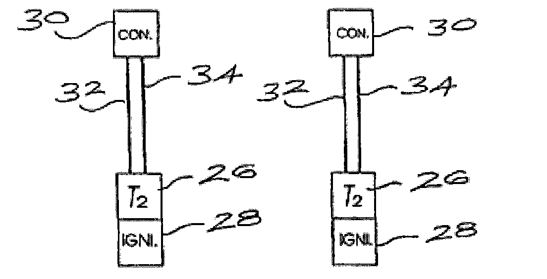
[0058] Such as Figure 1a As shown, the detonator system 10 provided by the embodiment of the present invention includes an electronic delay line 12 , a plurality of delay detonators 14 and a connector 30 for connecting the delay detonators 14 to the electronic delay line 12 .
[0059] refer to Figure 1b, the electronic time delay line 12 comprises several time delay relays 16, each time delay relay comprises a timer 16A and a control circuit 16B, these time delay relays 16 are connected together in series by electrical conductors or wires 18 and 20 of indeterminate length . The time-delay relays connected by wires 18 and 20 are separated from each other by a fixed distance 22, and the length of the distance 22 can be determined according to needs, for example, it can be 2m, 4m or any other selected length. The size of the distance 22 does not affect the understanding of the present invention, but it is very important in practical application and should be paid attention to....
Embodiment 2
[0072] The detonator system provided in this embodiment is basically the same as that in Embodiment 1, the difference lies in that the time delay relay used is different.
[0073] Figure 7 The delay relay used in this embodiment includes a voltage sensing circuit 16B, a delay timer 16A, and a switch driver 78 connected to one or more output switches 58 . The above-mentioned components are housed in the housing 68 . Also contained in the housing is a decoder 90 . If an input voltage signal Vin acts on the input terminals 60 and 62, the decoder 90 decodes and identifies the input voltage signal. If the input voltage signal is encoded correctly, the voltage sensor 16B is activated. At this time, the function of the delay relay is similar to that of the aforementioned delay relay. This way, the circuit only works when the correct code is detected.
[0074] The delay relay is further improved by providing an input terminal 92 on the timer 16B which allows connection of a prog...
Embodiment 3
[0077] FIG. 8 shows another detonator system 10A provided by this embodiment. Similar to FIG. 1 , the detonator system 10A includes: an electronic delay line 12 and a detonator 14 . The delay line has been manufactured in the factory. The time delay relay 16 connects the wires 18 and 20 in a predetermined manner.
[0078] The difference from the previous embodiments is that in this embodiment the detonator 14 is connected to the time delay relays rather than to a wire between adjacent time delay relays so that the detonator system 10A operates in a similar manner and has substantially the same characteristics .
PUM
 Abstract
Description
Claims
Application Information
 - R&D
- Intellectual Property
- Life Sciences
- Materials
- Tech Scout
- Unparalleled Data Quality
- Higher Quality Content
- 60% Fewer Hallucinations
Browse by: Latest US Patents, China's latest patents, Technical Efficacy Thesaurus, Application Domain, Technology Topic, Popular Technical Reports.
© 2025 PatSnap. All rights reserved.Legal|Privacy policy|Modern Slavery Act Transparency Statement|Sitemap|About US| Contact US: help@patsnap.com


