Eureka AIR delivers breakthrough ideas for toughest innovation challenges, trusted by R&D personnel around the world.

Flow-equalizing ventilation device

A technology of ventilation device and flow limiting device, which is applied in the direction of ventilation system, space heating and ventilation, heating and ventilation control system, etc. It can solve the problems of unfavorable adjustment of structure, difficulty of connection and sealing, and change of tuyere size, etc., and achieves simple structure , Easy to adjust, easy to operate

Active Publication Date: 2010-09-01
CHINA RAILWAY ERYUAN ENG GRP CO LTD
View PDF3 Cites 8 Cited by
  • Summary
  • Abstract
  • Description
  • Claims
  • Application Information

AI Technical Summary

Problems solved by technology

The above-mentioned ventilation flow equalizer can theoretically achieve the purpose of uniform air supply and uniform exhaust, but the actual operation process is complicated, and the adjustment structure is not conducive to adjustment
[0003] The tuyere is adjusted by rotation. Since the tuyere and the air supply and exhaust pipe are adjusted by movable rotation, it is difficult to connect and seal the tuyere and the air supply and exhaust pipe. The sealing effect is not ideal, and air leakage occurs at the connection. , thus affecting the uniform air supply and exhaust
[0004] Adjustment of the tuyere by telescopic connection is not conducive to the precise adjustment of the tuyere adjustment device, and the device is affected by the pressure of the air supply and exhaust during use, which may easily cause changes in the size of the tuyere, thus affecting the uniform air supply and exhaust

Method used


Image

  • Flow-equalizing ventilation device
  • Flow-equalizing ventilation device
  • Flow-equalizing ventilation device

Examples


Embodiment 1

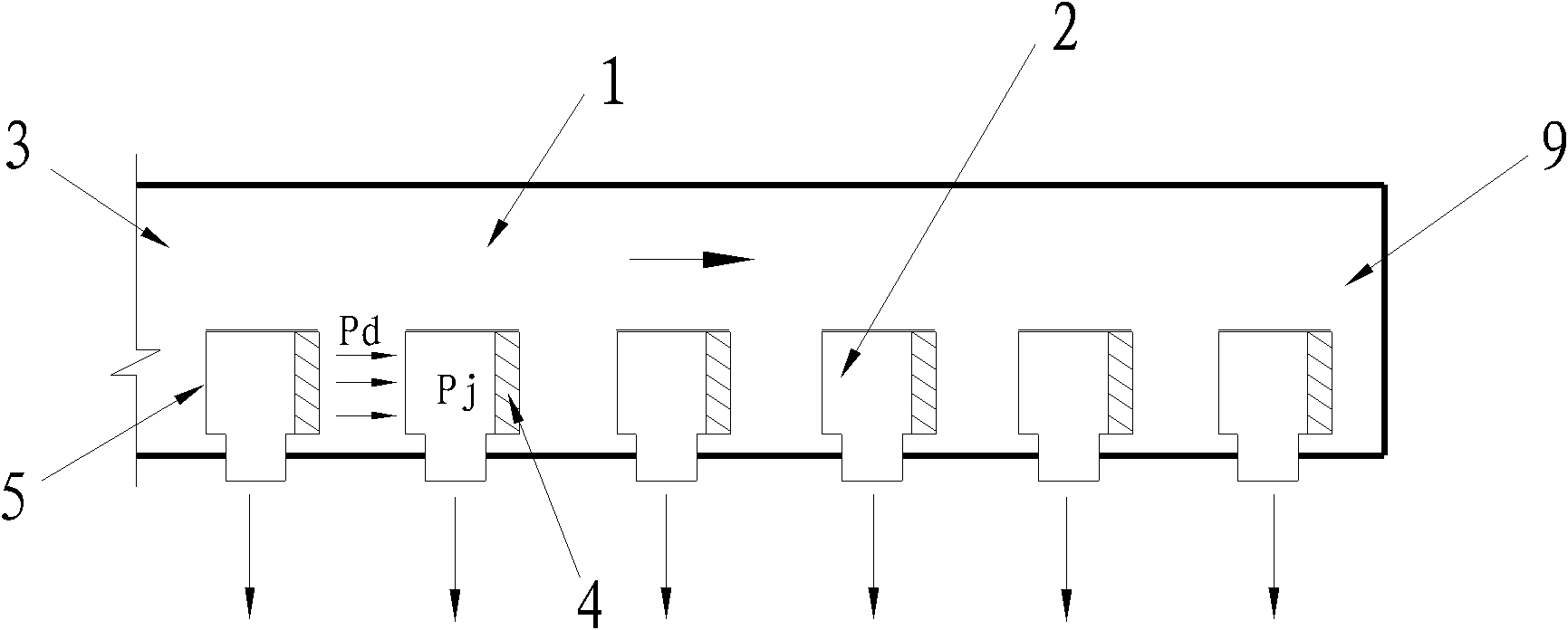
[0025] like figure 1 As shown, the ventilation duct 1 is an air supply duct, and a plurality of air outlets 2 are arranged on the air supply duct, and the air outlet 2 is a T-shaped pipe. Parallel and facing the open end 3 of the pipe, the end of all the tuyere 2 facing the windward section 5 is provided with a flow limiting device 4, that is, the windward section 5 and the flow limiting device 4 are respectively arranged at the two ends of the straight pipe on the upper part of the T-shaped pipe. The above-mentioned flow restricting device 4 may be a shutter valve or a flow restricting valve, and the opening amount of the flow restricting device 4 of the tuyere 2 arranged in sequence according to the opening ends 3 decreases sequentially.

[0026] In the air supply pipe, due to the flow of air in the pipe, there must be a dynamic pressure Pd consistent with the flow direction, and a static pressure Pj independent of the direction, and the total pressure in the pipe is the dyn...

Embodiment 2

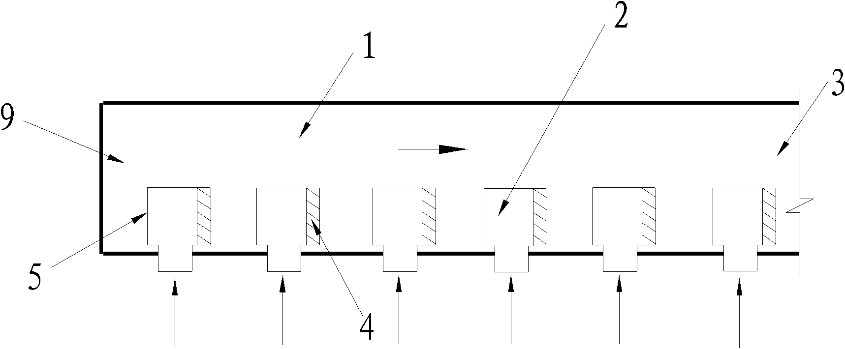
[0030] like figure 2 As shown, the ventilation duct 1 is an exhaust duct, and a plurality of air outlets 2 are arranged on the exhaust duct, and the air outlet 2 is a T-shaped pipe. In parallel and facing away from the open end 3 of the pipe, a flow limiting device 4 is provided on one end of all the tuyere 2 facing the windward section 5, that is, the windward section 5 and the flow limiting device 4 are respectively arranged on the two ends of the straight pipe on the upper part of the T-shaped pipe. The flow restricting device 4 can be a shutter valve or a flow restricting valve, and the opening amount of the flow restricting device 4 of the tuyere 2 arranged in sequence according to the open end 3 increases sequentially.

[0031] For the exhaust duct, the negative pressure inside each tuyere allows the outside air to flow into the ventilation duct from the tuyere to achieve the purpose of exhausting. On the one hand, since it is necessary to ensure that the tuyere farthe...

Embodiment 3

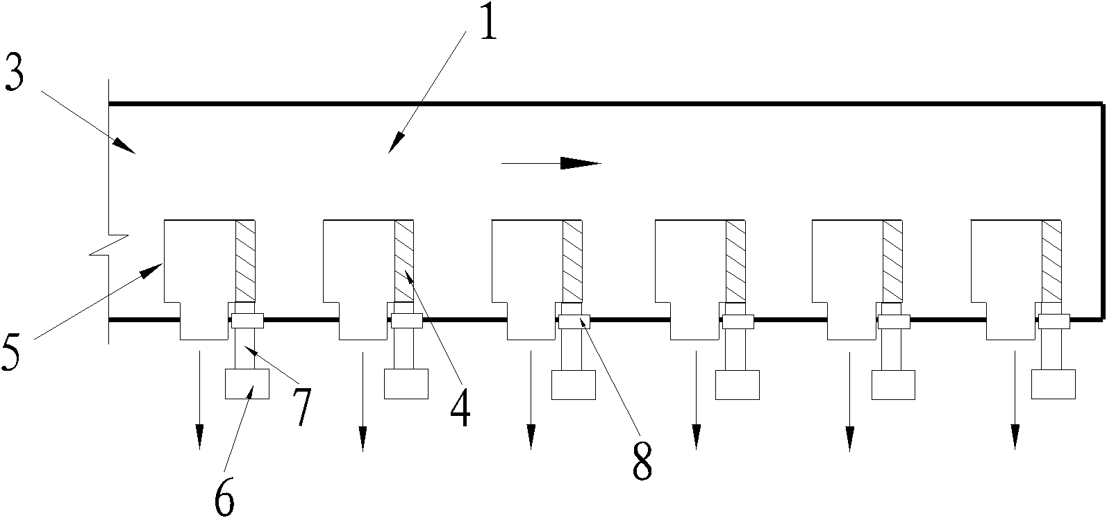
[0035] On the basis of Embodiment 1 or Embodiment 2, as image 3 and Figure 4 As shown, an opening amount adjusting device 7 is provided on the current limiting device 4, and the controller 6 of the adjusting device 7 for the opening amount of the current limiting device 4 is installed outside the air supply duct or the exhaust duct, through The controller 6 can adjust the opening amount of the flow restriction device 4, for example, the electric or manual controller of the adjustment device of the flow restriction valve is installed outside the pipeline, or the electric or manual controller of the adjustment device of the adjustment device for controlling the opening amount of the shutter valve is installed Installed outside the pipe, etc. With the above structure, the current limiting device can be adjusted more conveniently. Of course, the controller of the above-mentioned adjustment device can also be installed inside the air supply duct or the air exhaust duct, but thi...


PUM


Abstract

The invention discloses a flow-equalizing ventilation device, which is characterized by simple and convenient operation. The flow-equalizing ventilation device comprises a plurality of air openings arranged on a ventilation pipeline, wherein the ventilation pipeline comprises an opened end and a closed end, one air opening closest to the closed end of the ventilation pipeline belongs to the first group, other air gaps belong to the second group, windward sections of all the air openings are parallel to the section of the ventilation pipeline, a flow limiting device is arranged at least on each air opening in the second group and is specifically arranged on the other end corresponding to the end of the windward section; and the number of the opened flow limiting devices of the air openings arranged on the ventilation pipeline sequentially increases or decreases as the distance from the flow limiting devices to the farthest position of the closed end of the ventilation pipeline decreases gradually. The quantity and speed of airflows can be adjusted by adjusting the number of the opened flow limiting devices so as to realize uniform air supply and uniform air discharge, and simultaneously, the flow-equalizing ventilation device with simple and convenient operation can realize uniform air supply and discharge via simple adjusting and flow limiting devices.

Description

technical field [0001] The invention relates to a uniform flow ventilation device. Background technique [0002] At present, Chinese Patent No. 200710050238.5 discloses a ventilation equalizer, the device includes a plurality of tuyere installed on the ventilation duct. When the ventilation duct is an air supply duct, by adjusting each tuyere, the windward section of the tuyere faces the duct The open end of the air outlet, and the projected area of ​​the windward section of the tuyere arranged in sequence according to the open end on the section of the air supply duct is increased in turn, so as to finally achieve the purpose of uniform air supply; when the ventilation duct is an exhaust duct, by adjusting each The tuyere, so that the windward section of the tuyere is facing away from the open end of the pipe, and the projected area of ​​the windward section of the tuyere arranged in sequence according to the open end on the section of the air supply duct decreases in turn,...

Claims


Application Information

Patent Timeline
Patent Type & Authority Applications(China)
IPC IPC(8): F24F7/04F24F13/08F24F13/06F24F11/02
Inventor 钟星灿罗世培彭金龙石义军
Owner CHINA RAILWAY ERYUAN ENG GRP CO LTD
Why Eureka
Eureka Blog
Learn More