Bending resistance test device for valve
A strength test and anti-bending technology, applied in the mechanical field, can solve the problems of high cost, hidden safety hazards, difficult operation, etc., and achieve the effects of convenient operation, simple structure and accurate measurement values.
Inactive Publication Date: 2010-08-25
ZHEJIANG WORLD BRASS
View PDF5 Cites 11 Cited by
- Summary
- Abstract
- Description
- Claims
- Application Information
AI Technical Summary
Problems solved by technology
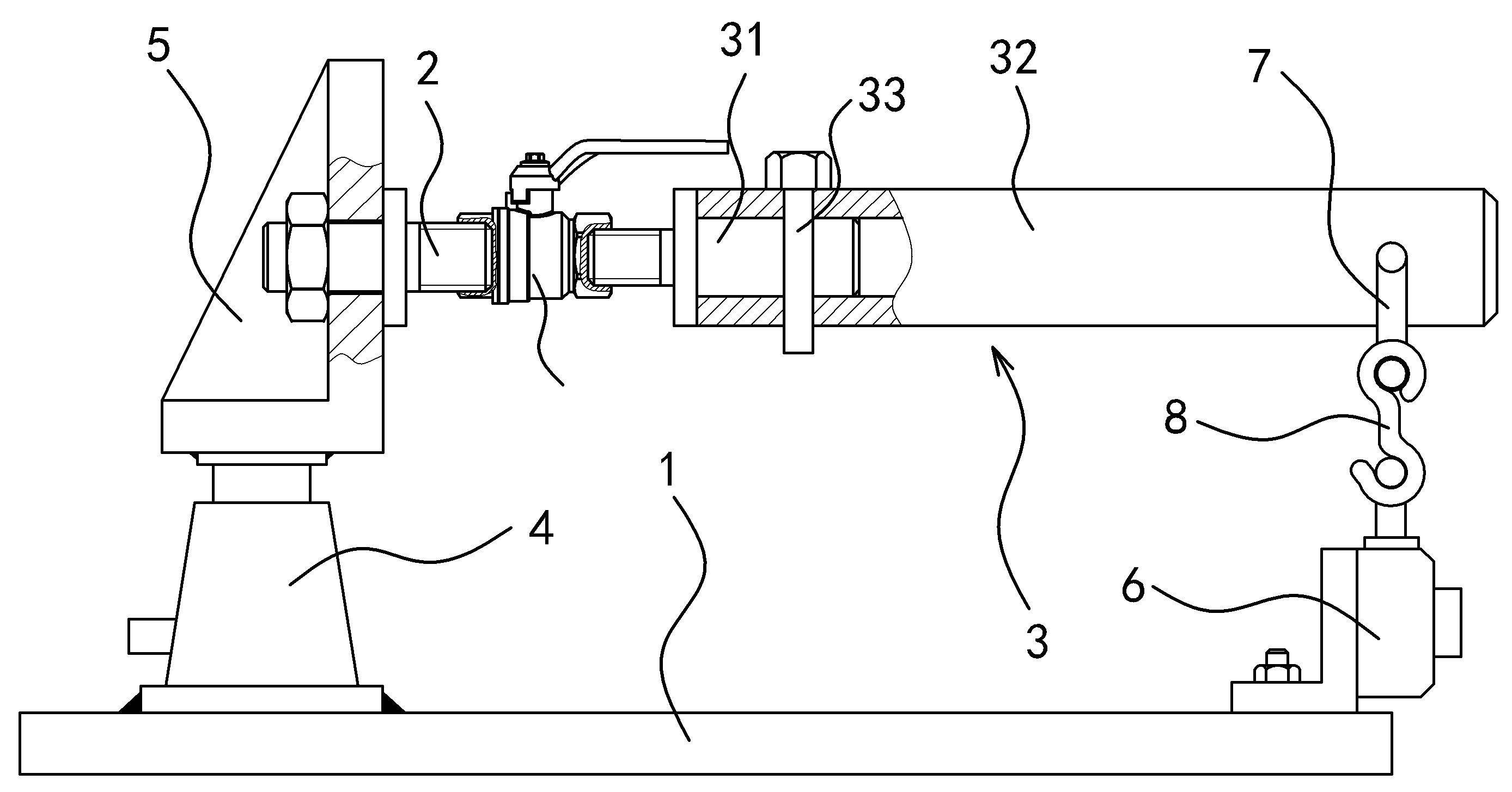
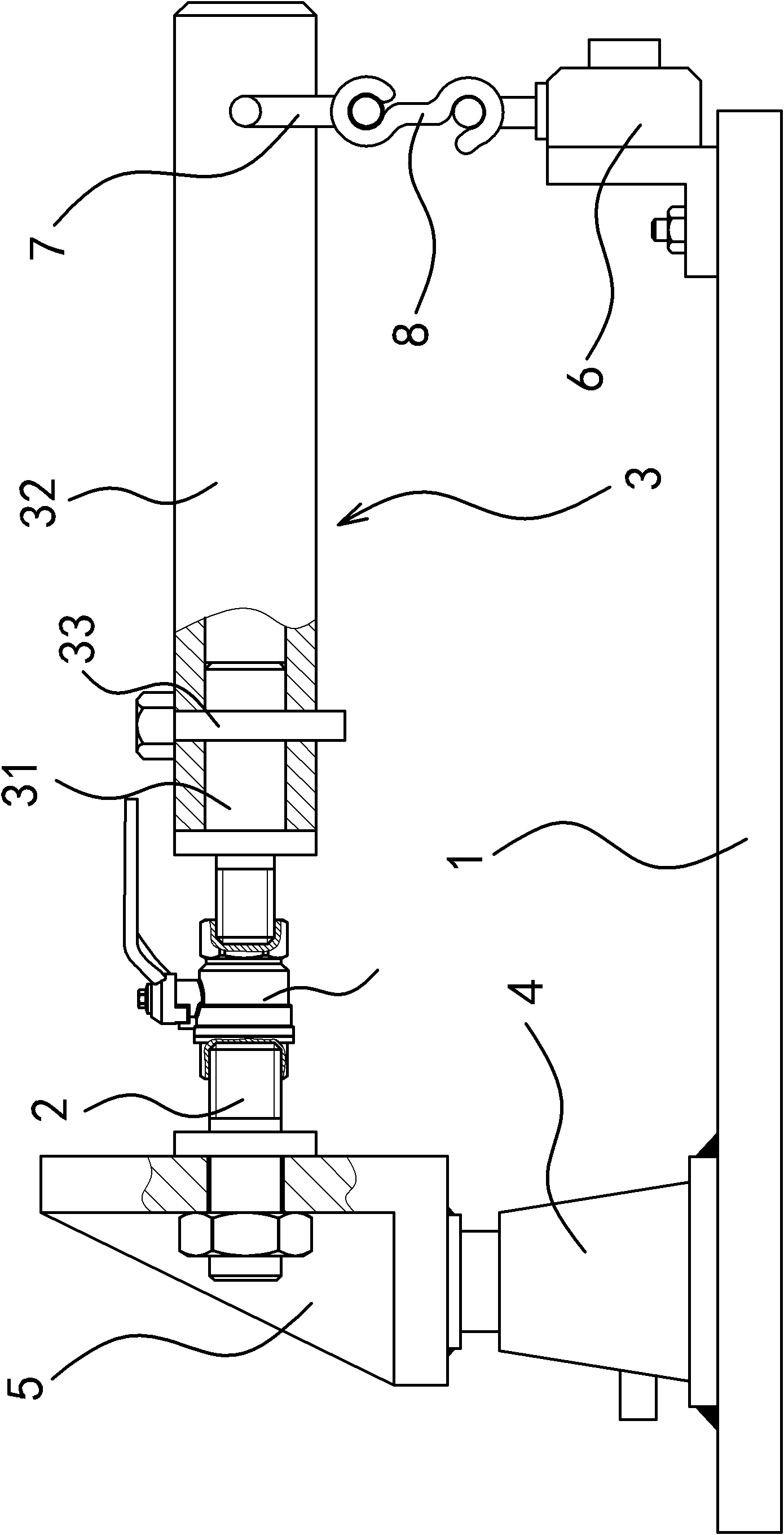
In the actual inspection process, first of all, a pipe fitting is generally tightened at both ends of the valve and supported at a suitable position; then an object of appropriate weight is used to act on the valve body. This traditional method is not only difficult to operate, but also costly. High, there are potential safety hazards at work
Method used
View moreImage
Smart ImageViewing Examples
Examples
Embodiment 1
Embodiment 2
Login to View More PUM
 Abstract
The invention provides a bending resistance test device for a valve, belonging to the technical field of machinery and solving the problems of difficult operation of the bending resistance of the traditional valve, high cost and potential safety hazard existing in operation. The bending resistance test device for the valve comprises a base, a connecting rod 1 and a connecting rod 2, wherein a force applying mechanism is fixed on the base, one end of the connecting rod 1 can be connected with one end of the valve and the other end can be fixedly connected with the force applying mechanism, the force applying mechanism can ensure the connecting rod 1 to bear a radial action force when the force applying mechanism is operated; and one end of the connecting rod 2 can be connected with the other end of the valve, and a force measurer capable of measuring a radial force-loading value of the connecting rod 2 is arranged between the other end of the connecting rod 2 and the base. The bending resistance test device for the valve has the advantages of simple structure, small occupation space, convenient operation and accurate measurement values.
Description
Valve bending strength test device technical field The invention belongs to the technical field of machinery, and relates to a test device, in particular to a valve bending resistance test device. Background technique Valves are one of the commonly used engineering components in people's life and production. With the development of society and the advancement of science and technology, products are not only updated and upgraded, but also product quality testing has been widely valued. The country has promulgated relevant testing specifications for the testing standards of valves. For the bending resistance test of valves, GB / T8464-2008 has made a clear description, but the specific equipment used has not been explained in detail. In the actual inspection process, first of all, a pipe fitting is generally tightened at both ends of the valve and supported at a suitable position; then an object of appropriate weight is used to act on the valve body. This traditional method i...
Claims
Login to View More Application Information
Patent Timeline
 Patent Type & Authority Applications(China)
IPC IPC(8): G01M19/00G01M99/00
Inventor 卓旦春
Owner ZHEJIANG WORLD BRASS
Features
- R&D
- Intellectual Property
- Life Sciences
- Materials
- Tech Scout
- Unparalleled Data Quality
- Higher Quality Content
- 60% Fewer Hallucinations
Learn More Browse by: Latest US Patents, China's latest patents, Technical Efficacy Thesaurus, Application Domain, Technology Topic, Popular Technical Reports.
© 2025 PatSnap. All rights reserved.Legal|Privacy policy|Modern Slavery Act Transparency Statement|Sitemap|About US| Contact US: help@patsnap.com


