Ball valve motion track positioning control type oil-well pump valve assembly
A motion trajectory, positioning control technology, applied in the direction of variable displacement pump components, pump components, machines/engines, etc., can solve the problems of small flow area, hard collision damage between the ball and the upper ball block, and increasing the downward resistance of the plunger. , to achieve the effect of reducing the flow resistance of the liquid inlet, avoiding side hits, and reducing the downward resistance
Inactive Publication Date: 2010-08-25
李光献 +1
View PDF10 Cites 1 Cited by
- Summary
- Abstract
- Description
- Claims
- Application Information
AI Technical Summary
Problems solved by technology
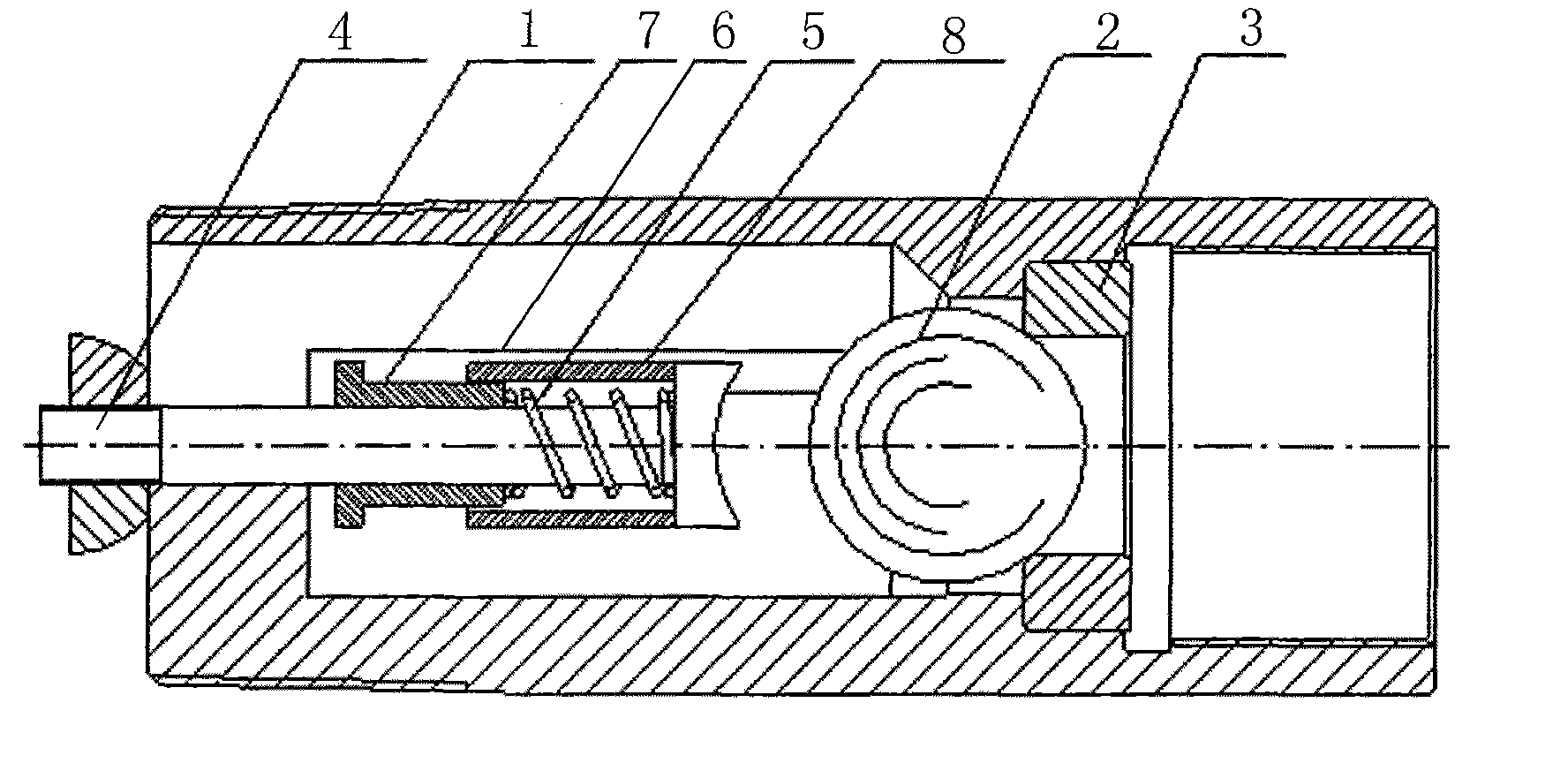
The oil well pump is a necessary equipment in the field of oil production. The balls of the oil well pumps currently used are not positioned in the valve cover when they jump up and fall. Due to the high formation pressure, the ball balls directly collide with the valve cover when they jump up and fall. The damage caused by the hard collision between the sphere and the upper ball stopper; when the ball ball jumps up and falls, it will drift left and right and cannot move along the axis. In addition, when the ball ball jumps up, part of the liquid outlet is blocked, and the flow area is small, that is Increased downward resistance of the plunger
Method used
View moreImage
Smart ImageViewing Examples
Examples
Embodiment Construction
Login to View More PUM
 Abstract
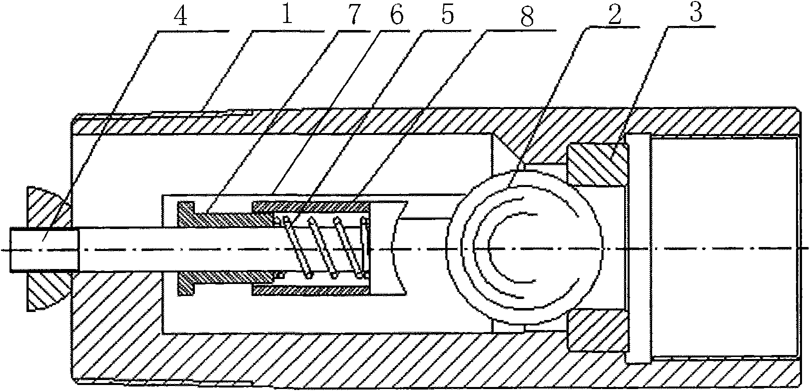
The invention relates to a ball valve motion track positioning control type oil-well pump valve assembly, which comprises a valve housing (1) and a valve ball (2), wherein a valve seat (3) is arranged in the valve housing (1); the valve ball (2) is positioned above the valve seat (3); a power valve (4) is arranged in the top center of an inner cavity of the valve housing (1); the lower end surface of the power valve (4) is a semicircle spherical surface and corresponds to the valve ball (2); the power valve (4) and the valve housing (1) can relatively slide; and an elastic part (5) for resetting the power valve (4) is arranged on the power valve (4). The positioning control mechanism prolongs the service life of the valve assembly, keeps a large flow channel to reduce feed liquid flow resistance, accelerates the closing speed of the ball valve to reduce the leakage and improves the pump efficiency.
Description
Ball valve motion track positioning control type oil pump valve assembly Technical field: The invention belongs to an oil well pump in the field of oil extraction, in particular to a ball valve movement track positioning control type oil well assembly. Background technique: The oil well pump is a necessary equipment in the field of oil production. The oil well ball used at present has no positioning in the valve cover. Due to the high formation pressure, the ball directly collides with the impact valve cover when it jumps and falls. The damage caused by the hard collision between the sphere and the upper ball block; when the ball jumps and falls, it will drift left and right and cannot move along the axis. In addition, when the ball jumps, the liquid outlet is partially blocked, and the flow area is small, that is Increase the downward resistance of the plunger. Summary of the invention: In order to solve the problems existing in the background technology, the present invent...
Claims
Login to View More Application Information
Patent Timeline
 Patent Type & Authority Applications(China)
IPC IPC(8): F04B53/10
Inventor 李延鹏李庆国范云泽徐亚萍王智超王景武俞博洋
Owner 李光献
- R&D Engineer
- R&D Manager
- IP Professional
- Industry Leading Data Capabilities
- Powerful AI technology
- Patent DNA Extraction
Learn More Browse by: Latest US Patents, China's latest patents, Technical Efficacy Thesaurus, Application Domain, Technology Topic, Popular Technical Reports.
© 2024 PatSnap. All rights reserved.Legal|Privacy policy|Modern Slavery Act Transparency Statement|Sitemap|About US| Contact US: help@patsnap.com


