
Tiled passive matrix electro-luminescent display

A technology of passive matrix and display, applied in the field of passive matrix electroluminescence display

Active Publication Date: 2010-08-18
GLOBAL OLED TECH
View PDF19 Cites 14 Cited by
  • Summary
  • Abstract
  • Description
  • Claims
  • Application Information

AI Technical Summary

Problems solved by technology

Notably, these methods only correct for differences between the optical properties of adjacent tiles

Method used


Image

  • Tiled passive matrix electro-luminescent display
  • Tiled passive matrix electro-luminescent display
  • Tiled passive matrix electro-luminescent display

Examples


example 1

[0049] Example 1: Comparing

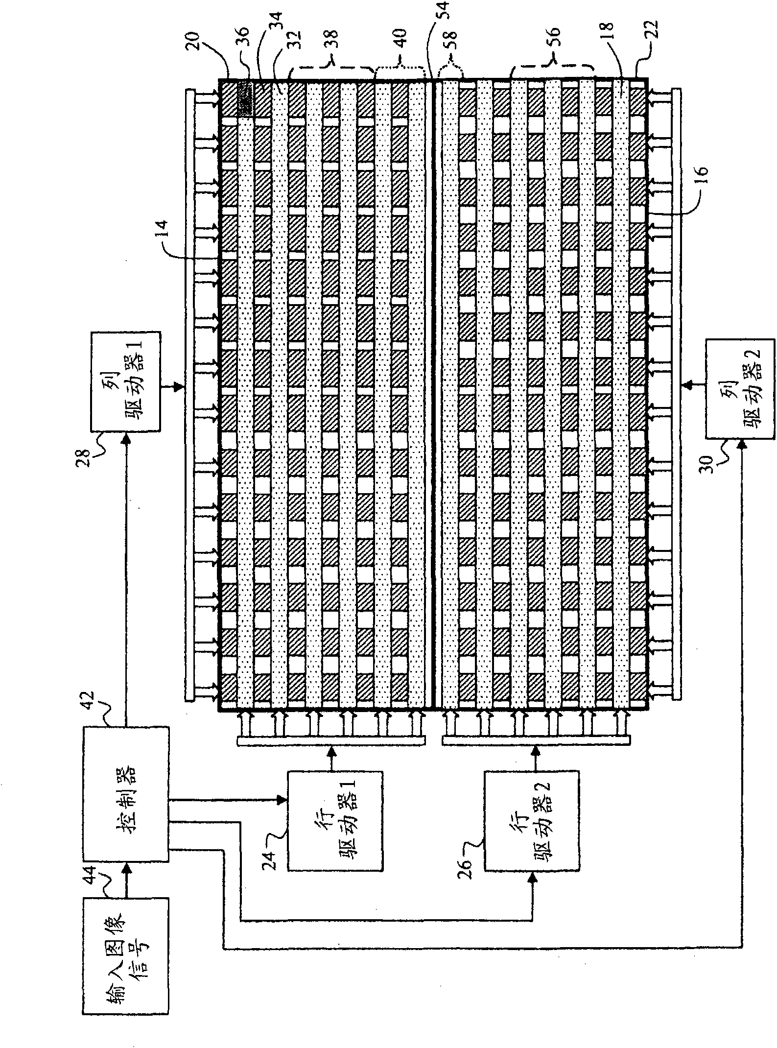
[0050] In this example, it is assumed that the display has two tiles 20 , 22 each having 120 row electrodes 32 and 240 column electrodes 34 . Also, assume that each tile has its own row and column drivers. In addition, each tile has its own controller 42, and each controller receives only the portion of the input image signal 44 corresponding to the spatial position of the light emitting element 36 within the tile 20, 22 it controls. Consequently, both controllers are unable to respond to brightness variations within the input image signal that occur in the input image signal, the brightness variations corresponding to the spatial positions of the light emitting elements in adjacent tiles. This design is consistent with prior art implementations where the input image signal is parsed and passed to tiles for presentation.

[0051] The input image signal 44 includes information for rendering two dark gray bars on a white background. The dark gray...

example 2

[0053] Example 2: Invented

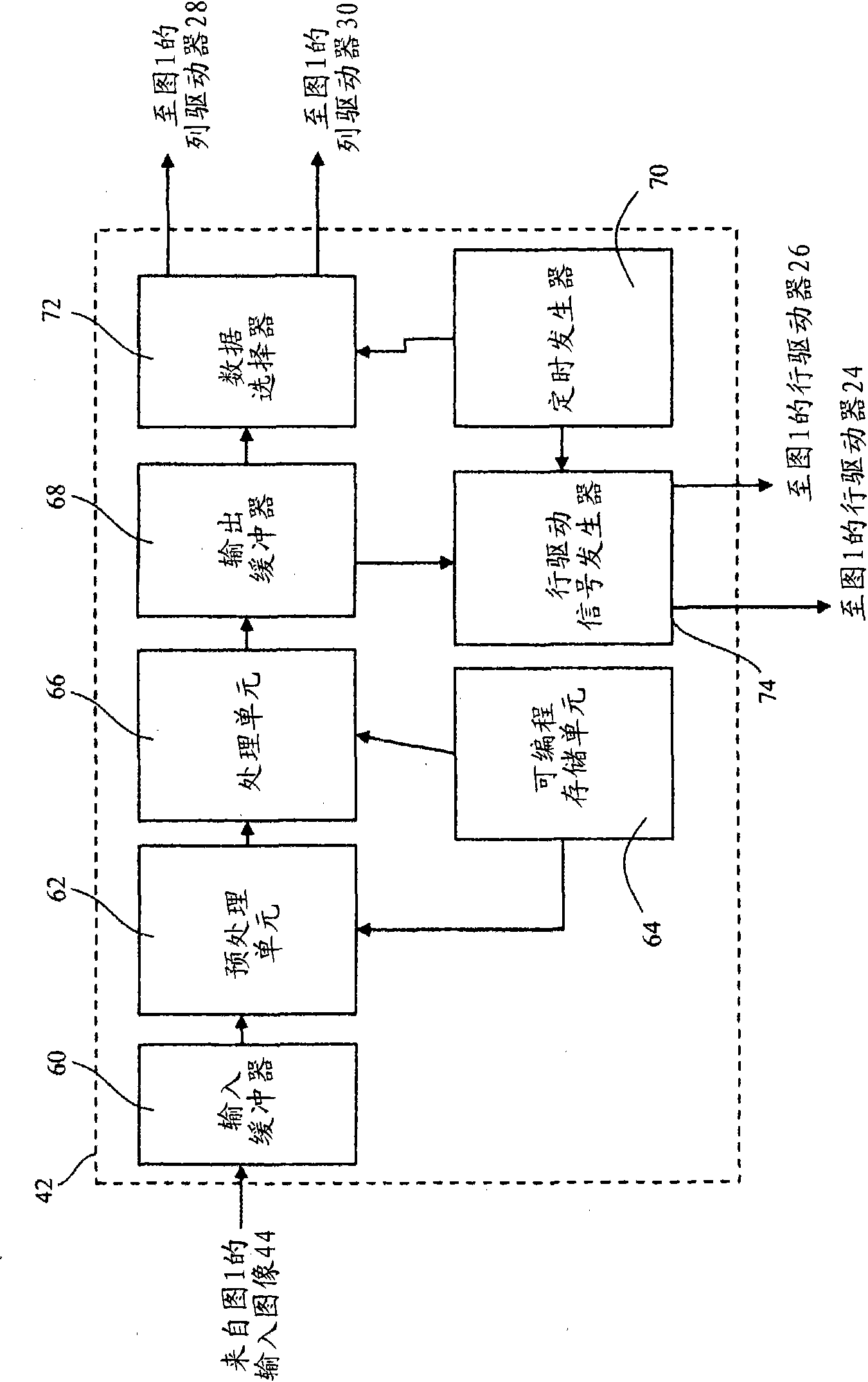
[0054] In this example, a tiled passive matrix EL display was created according to one embodiment of the invention. It comprises two EL tiles, each EL tile comprising an array of 120 rows by 240 columns of light emitting elements, each light emitting element being formed by a light emitting layer sandwiched between an orthogonal array of row and column electrodes. A tiled passive matrix EL display includes at least one row and column driver for controlling the flow of electrons between row and column electrodes within each tile to control light emission from each light emitting element within each tile. It is assumed that the tiled passive matrix EL display further includes a controller connected to the row driver and the column driver, the controller is used to receive the input image signal and send Each row driver provides a predetermined number of row drive signals with a first exception that the number of row drive signals is less than the pr...


PUM


Abstract

A tiled, passive-matrix, EL display, including two or more EL tiles, each EL tile including an array of rows and columns of light-emitting elements, each light-emitting element being formed from a light-emitting layer that is sandwiched between an orthogonal array of row and column electrodes wherein each of the two or more EL tiles further include at least one row driver; at least one column driver for operating in conjunction with each of the at least one row drivers to control the flow of electrons between the row and column electrodes to control the emission of light from each of the light-emitting elements, with a first exception that when the boundary between the two tiles is to be illuminated, then the number of rows of simultaneously illuminated rows of light-emitting elements within one tile is less than the predetermined number.

Description

technical field [0001] The present invention relates to passive matrix electroluminescent displays. In particular, the present invention relates to tiled passive matrix displays that, when driven, have no visible borders between adjacent tiles. Background technique [0002] There are many display devices on the market today. Among the available displays are thin-film coated electroluminescent (EL) displays, such as OLED displays. These displays can be driven using an active matrix backplane, which utilizes an active circuit array. These active circuits control the flow of current to the various light emitting elements in the display. However, these displays are relatively expensive due to the complexity of forming the active circuitry on each light-emitting element, and the thin-film transistors often used in these active drive circuits are prone to defects, resulting in lack of uniformity or time-varying threshold shift, thereby deteriorating the quality of the display....

Claims


Application Information

Patent Timeline
Patent Type & Authority Applications(China)
IPC IPC(8): G09G3/32
CPCG09G2300/026H01L27/3281G09G2330/021G09G2320/0233G09G2310/0205H01L27/3293G09G2310/021G09G3/3216G09G2310/0221G09G2300/06H10K59/17H10K59/18
Inventor 迈克尔·尤金·米勒安德鲁·丹尼尔·阿诺德约翰·富兰克林·小汉密尔顿
Owner GLOBAL OLED TECH
Learn More