Monitoring system, method and device thereof for filtering alarm

A monitoring system and alarm device technology, which is applied in transmission systems, digital transmission systems, alarms, etc., can solve problems such as troublesome use, damage to instruments, and lower recognition of security systems, so as to facilitate promotion, reduce resource waste, and improve The effect of alert efficiency

Inactive Publication Date: 2010-08-18
SHENZHEN XBROTHER TECH
View PDF3 Cites 11 Cited by
  • Summary
  • Abstract
  • Description
  • Claims
  • Application Information

AI Technical Summary

Problems solved by technology

[0003] When the alarm device sends an alarm, it basically sends an alarm message to the server when the device fails or there are other emergencies, but often the same situation will cause multiple device alarms, for example, when there is a fire in the computer room When the power is cut off, the air conditioner in the computer room will fail, the control instrument on the operation platform will fail, etc. When the above equipment fails at the same time, it is necessary to send an alarm message to the server. For example, the air conditioner needs to send an alarm message to the server. The alarm information of the work, the various instruments on the operation platform send the alarm information of the instrument damage to the server, of course, the fire alarm will also send the fire alarm information to the server
[0004] When a large number of alarm messages are sent out at the same time due to the same reason, it is difficult for the user to judge which alarm messages must be dealt with urgently and which alarm messages do not need to be dealt with immediately. Once the judgment is wrong, the unnecessary alarm messages will be dealt with first , and the necessary alarm information cannot be processed in a timely manner, which will bring great trouble to the user's use, and then reduce the user's recognition of the security system

Method used


Image

  • Monitoring system, method and device thereof for filtering alarm
  • Monitoring system, method and device thereof for filtering alarm
  • Monitoring system, method and device thereof for filtering alarm

Examples


Embodiment Construction

[0020] In order to make the object, technical solution and advantages of the present invention clearer, the present invention will be further described in detail below in conjunction with the accompanying drawings and embodiments. It should be understood that the specific embodiments described here are only used to explain the protection scope of the present invention, and should not be used to limit the protection scope of the present invention.

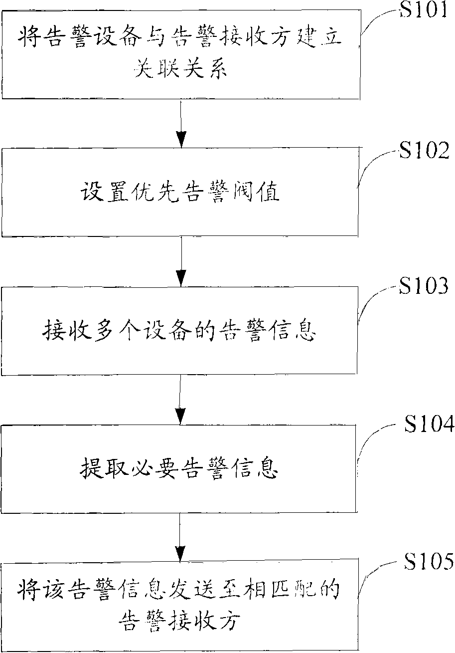
[0021] figure 1 The flow of the alarm filtering method of the monitoring system provided by the embodiment of the present invention is shown.

[0022] Step S101, establishing an association relationship between the alarm device and the alarm receiver, wherein the alarm receiver only receives the alarm information of the alarm device associated with it.

[0023] For example, if the air conditioner ① in the computer room is associated with the extension number 2201 of the user, the extension 2201 will only receive the alarm informati...


PUM


Abstract

The invention is applicable to the field of machine room monitoring, and discloses a monitoring system, and a method and a device thereof for filtering alarm. The method comprises the following steps: receiving alarm information of multiple alarm devices; based on a prior alarm threshold value stored in a system, extracting alarm information matched with the prior alarm threshold value from the multiple pieces of alarm information; and based on alarm receiving party information set in the system, which is associated with the alarm information, sending the alarm information to the alarm receiving party. By simply sending necessary alarm information to the corresponding alarm receiving party, the invention effectively avoids unnecessary alarm information, reduces the resource water rate, and improves the alarm efficiency of the monitoring system, thereby being beneficial to the popularization of the monitoring system.

Description

technical field [0001] The invention belongs to the field of machine room monitoring, and in particular relates to a filtering alarm method, device and monitoring system of a monitoring system. Background technique [0002] With the continuous development of security monitoring technology, users have higher and higher requirements for security monitoring. The monitoring system in the prior art generally includes several monitored devices connected by communication. These monitored devices may be different in different systems. The monitored device is generally connected to the server through a network interface or a serial port to provide alarm information, so that the server can process the alarm information and send a reminder call or message to relevant personnel. [0003] When the alarm device sends an alarm, it basically sends an alarm message to the server when the device fails or there are other emergencies, but often the same situation will cause multiple device ala...

Claims


Application Information

Patent Timeline
IPC IPC(8): H04L12/24G08B25/00
Inventor 胡毅
Owner SHENZHEN XBROTHER TECH
Why Eureka
Try Eureka