
Method for controlling a crane

A technology of cranes and machinery, which is applied in the direction of clockwork mechanism, load hanging components, hoisting device, etc., which can solve the problems of short service life of ropes and achieve the effect of prolonging and improving service life

Active Publication Date: 2010-08-04
KONECRANES GLOBAL
View PDF0 Cites 10 Cited by
  • Summary
  • Abstract
  • Description
  • Claims
  • Application Information

AI Technical Summary

Problems solved by technology

In addition, the rope has a very short service life as it is wound on the reel with great force

Method used


Image

  • Method for controlling a crane
  • Method for controlling a crane
  • Method for controlling a crane

Examples


Embodiment Construction

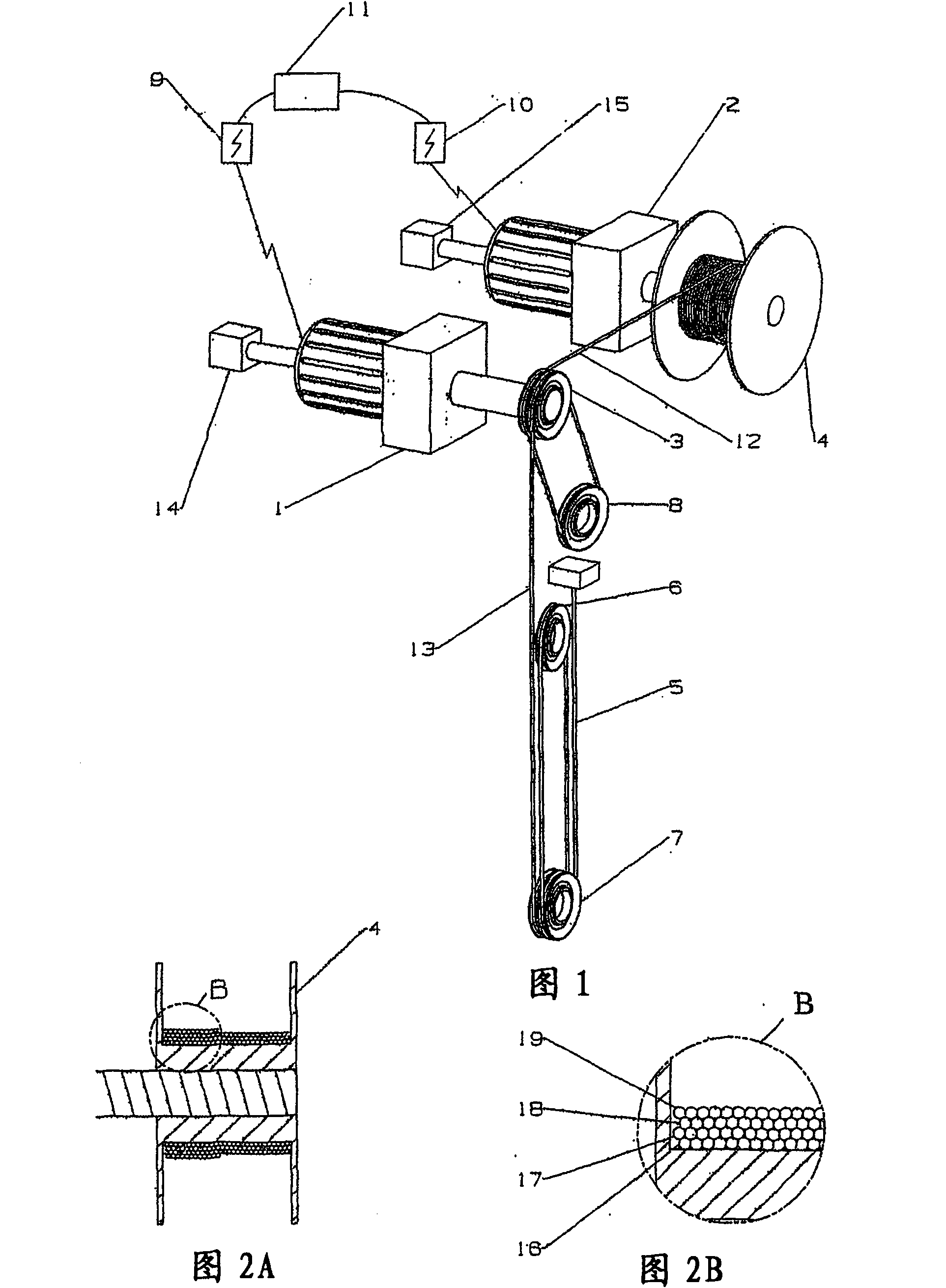
[0015] figure 1 The structure of the crane used in the method of the invention is shown in more detail. Part 1 and Part 2 are mechanical devices. The mechanical part 1 is driven by an electric drive 9 and the mechanical part 2 by an electric drive 10 . The electric drive is usually a variable frequency drive, but a similar invention can also be realized with a DC drive. The mechanism 1 drives the friction drive wheel 3 and the mechanism 2 drives the storage reel 4 . Pulley 8 is used to obtain a large enough rope grip angle. Increasing the grip angle increases friction. The pulley system 6 and 7 constitutes a conventional rope drive for reducing the required rope force. The hook of the crane (not shown) is fastened to the lower pulley system 7 . The rope portion 5 is fastened to a fixed point of the crane superstructure. The shaft of the mechanism includes angle sensors 14 and 15 which provide velocity and position information of the mechanism. In particular, location i...


PUM


Abstract

The invention relates to a method for controlling a crane, the method comprising controlling a rope part (13) connected to a hook of the crane with a friction- operated driving wheel (3), extra rope (12) being coiled into a plurality of layers onto a storage reel (4). In the method, two machineries (1, 2) are used, of which the first (1 ) is intended for the driving wheel (3) and the other (2) for the storage reel (4), one machinery (1, 2) being controlled with a speed instruction and the other machinery (1, 2) with a torque instruction.

Description

technical field [0001] The invention relates to a method for controlling a crane, the method comprising controlling a portion of rope connected to the hook of the crane by means of a friction drive wheel, the rich rope is wound in multiple layers on a storage reel, wherein two mechanical devices are used, the first One mechanism is used to drive the wheels and another mechanism is used to store the reels. Background technique [0002] In lifting gear, the sling is usually wound in one layer on a drum when the lifting hook is in the high position. However, other methods are also known - in which a rich rope is wound on a storage scroll. In these methods, sufficient friction can be achieved via the drive wheel and the pulley, whereby only a small force, eg via a helical spring, is required to tension the rope on the storage wheel. One method is to wind the rope in multiple layers directly on the drive drum. [0003] However, especially when the hoisting height is particular...

Claims


Application Information

Patent Timeline
Patent Type & Authority Applications(China)
IPC IPC(8): B66D1/12B66D1/40B66C13/22
CPCB66D1/7405B66D1/46B66C13/23B66D1/12B66D1/40B66D1/7415
Inventor M·波玛J·霍夫伦
Owner KONECRANES GLOBAL
Learn More