
Method for processing kitchen waste and equipment thereof

A technology of kitchen waste and treatment equipment, which is applied in the direction of combustion method, separation method, lighting and heating equipment, etc., can solve people's health hazards, environmental pollution and other problems, and achieve the effect of simple operation and simple structure

Active Publication Date: 2010-08-04
HANYU GRP CO LTD
View PDF6 Cites 11 Cited by
  • Summary
  • Abstract
  • Description
  • Claims
  • Application Information

AI Technical Summary

Problems solved by technology

The domestic garbage mixing equipment commonly used in daily life will produce more gas during the mixing process, and these gases are mainly composed of toxic gases (such as CO, HC and NO X Etc.) and odor, direct discharge of these toxic gases into the air will not only cause great harm to people's health, but also cause environmental pollution
The domestic waste mixing equipment currently on the market, especially the kitchen waste mixing equipment, has no relevant structure to deal with the generated gas. The existing kitchen waste mixing equipment directly discharges the gas generated during the mixing process. all in the air

Method used


Image

  • Method for processing kitchen waste and equipment thereof
  • Method for processing kitchen waste and equipment thereof
  • Method for processing kitchen waste and equipment thereof

Examples


Embodiment Construction

[0030] Provide the best embodiment of the present invention below in conjunction with accompanying drawing.

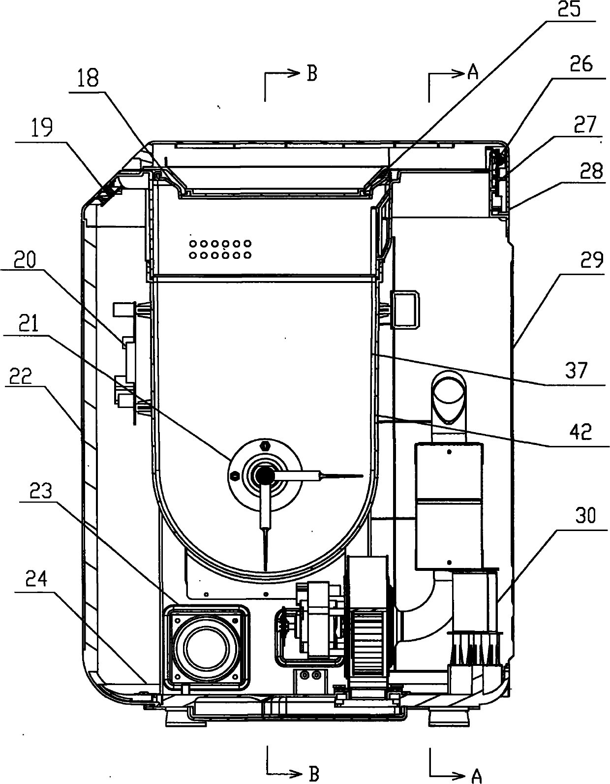
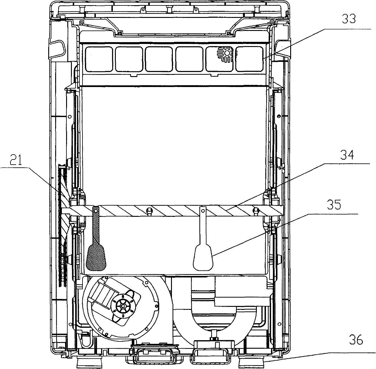
[0031] The embodiment of the present invention relates to a kitchen waste treatment method and its equipment, the specific structure of which equipment is: a kitchen waste treatment equipment, such as figure 1 , figure 2 As shown, a housing is formed by cover assembly 1, front shell 22, left side plate 6, right side plate 17, rear cover plate 29 and base 24; The pin is hinged on the back cover, and the pin is fixed with the shaft support plate 27 located on the back cover. A mixing tank 37 is installed in the housing, a middle seat 2 is provided between the mixing tank and the charging cover, the middle seat and the middle seat rear cover 28 are fixed on the rear cover, and the bottom edge ring of the charging cover is provided with a sealing strip 25 and the middle The seat is matched with each other, and the mixing tank and the feeding cover are sealed with a seal...


PUM


Abstract

The invention discloses equipment for processing kitchen waste. In the equipment, a shell consists of a cover assembly, a front casing, a left side plate, a right side plate, a rear cover plate, a feeding cover and a base; a stirring vessel and a stirring motor are arranged in the shell; a stirring shaft driven by the motor is inserted into the center of the stirring vessel; a stirring rod is fixedly arranged on the stirring shaft; a sealing strip is arranged between the stirring vessel and the feeding cover for sealing; a photocatalyst assembly which is communicated with a gas outlet in the middle-upper part of the inner chamber of the stirring vessel by a first elbow pipe is arranged in the shell; the other end of the photocatalyst assembly is sequentially connected in series with a second elbow pipe, a first catalyst tank, a third elbow pipe and a second catalyst tank which are arranged in the shell in a communication way; and the other end of the second catalyst tank is provided with a fourth elbow pipe which is connected with a second air blower. The invention also discloses a method for processing the kitchen waste. The method comprises the steps of placing the kitchen waste and digestive bacteria into the stirring vessel; starting the stirring motor and heating the stirred materials to the temperature of about 50 DEG C; and allowing gases to enter a gas processing system through negative pressure of the first air blower, and then exhausting the gases.

Description

Technical field: [0001] The invention relates to a processing method for domestic kitchen waste and its mechanical equipment, belonging to the field of domestic waste treatment. Background technique: [0002] There are many kinds of mixing equipment at present, and the structures are different. The domestic garbage mixing equipment commonly used in daily life will produce more gas during the mixing process, and these gases are mainly composed of toxic gases (such as CO, HC and NO X etc.) and odor, directly discharging these toxic gases into the air will not only cause great harm to people's health, but also cause environmental pollution. The domestic waste mixing equipment currently on the market, especially the kitchen waste mixing equipment, has no relevant structure to deal with the generated gas. The existing kitchen waste mixing equipment directly discharges the gas generated during the mixing process. all in the air. [0003] Due to the existence of many defects in ...

Claims


Application Information

Patent Timeline
IPC IPC(8): B01J19/18B01D53/86F23G7/07
Inventor 石华山马俊涛林卫文
Owner HANYU GRP CO LTD
Learn More