
Power governor and control method thereof

A power conditioner and control signal technology, applied in the direction of adjusting electrical variables, control/regulating systems, output power conversion devices, etc., can solve the problems of harmonic need compensation, complex circuit structure, complex filter circuit design, etc., to achieve switching The effect of constant frequency, reduced circuit cost, and enhanced stability

Active Publication Date: 2010-07-28
SILERGY SEMICON TECH (HANGZHOU) CO LTD
View PDF4 Cites 16 Cited by
  • Summary
  • Abstract
  • Description
  • Claims
  • Application Information

AI Technical Summary

Problems solved by technology

[0007] In view of the above-mentioned defects, the purpose of the present invention is to provide a power regulator to solve the technical problems in the prior art that harmonics need to be compensated or the circuit structure to achieve a fixed frequency is too complicated
[0008] The present invention also provides a control method of a power regulator to solve the technical problems of complex design of filter circuits in the prior art or the existence of harmonics that need to be compensated

Method used


Image

  • Power governor and control method thereof
  • Power governor and control method thereof
  • Power governor and control method thereof

Examples


Embodiment 1

[0044] Figure 6A Shown is a functional block diagram of the fixed time generating circuit 5 according to an embodiment of the present invention. Figure 6B shown as Figure 6A working waveform.

[0045] Figure 6A The shown fixed time generating circuit 5 includes three parts: a reference voltage generating module 51 , a ramp signal generating module 52 and a comparing module 53 .

[0046] The reference voltage generating module 51 is composed of a switching circuit and an averaging circuit; the switching circuit receives a PWM control signal and a reference source signal, and the averaging circuit performs an averaging operation on the received PWM control signal.

[0047] The comparison module 53 of this embodiment is realized by a comparator 609 .

[0048] The switch circuit includes an inverter 612, a first transistor 601, and a second transistor 602;

[0049] The averaging circuit includes a resistor 611 and a first capacitor 621; wherein the gate of the second tran...

Embodiment 2

[0072] Please refer to Figure 7A with Figure 7B , is a functional block diagram of the fixed time generating circuit 5 according to another embodiment of the present invention. Figure 7B shown as Figure 7A working waveform.

[0073] Figure 7A The preferred fixed time generation circuit shown generally includes three parts: a reference voltage generation module 51 , a ramp signal generation module 52 and a comparison module 53 .

[0074] The reference voltage generating module 51 may be composed of a switch circuit and an average circuit; the switch circuit receives the PWM control signal, and the average circuit performs an average operation on the received PWM control signal;

[0075] Same as the first embodiment, the comparison module 53 is realized by a comparator 609 .

[0076] The switch circuit includes an inverter 612, a first transistor 601, and a second transistor 602;

[0077] The averaging circuit includes a resistor 611 and a first capacitor 621;

[007...


PUM


Abstract

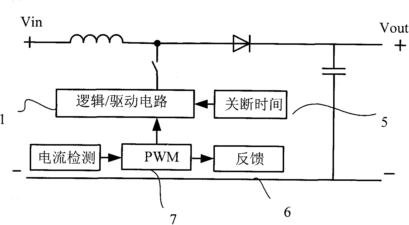
The invention discloses a power governor and an adjusting method based on circuits. The power governor comprises a power level circuit, a switch device adjustment signal generating circuit, a fixed time generating circuit and a logic / drive circuit, wherein the fixed time generating circuit receives PWM (pulse width modulation) control signals and generates fixed time signals according to the duty cycle of the PWM control signals; and the logic / drive circuit controls the action of a switch device in the power level circuit to adjust output signals and keep the working frequency of the switch device constant. The adjusting method which is based on the power governor and adopts the circuits of the power governor can realize on-off of the switch device or constant turn-on time and ensure the constant switching frequency, thereby simplifying the design of an EMI (electromagnetic interference) filter circuit, reducing the circuit cost, reducing interference to other circuits and improving the stability of the power governor.

Description

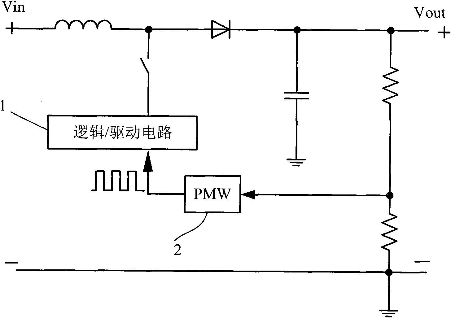
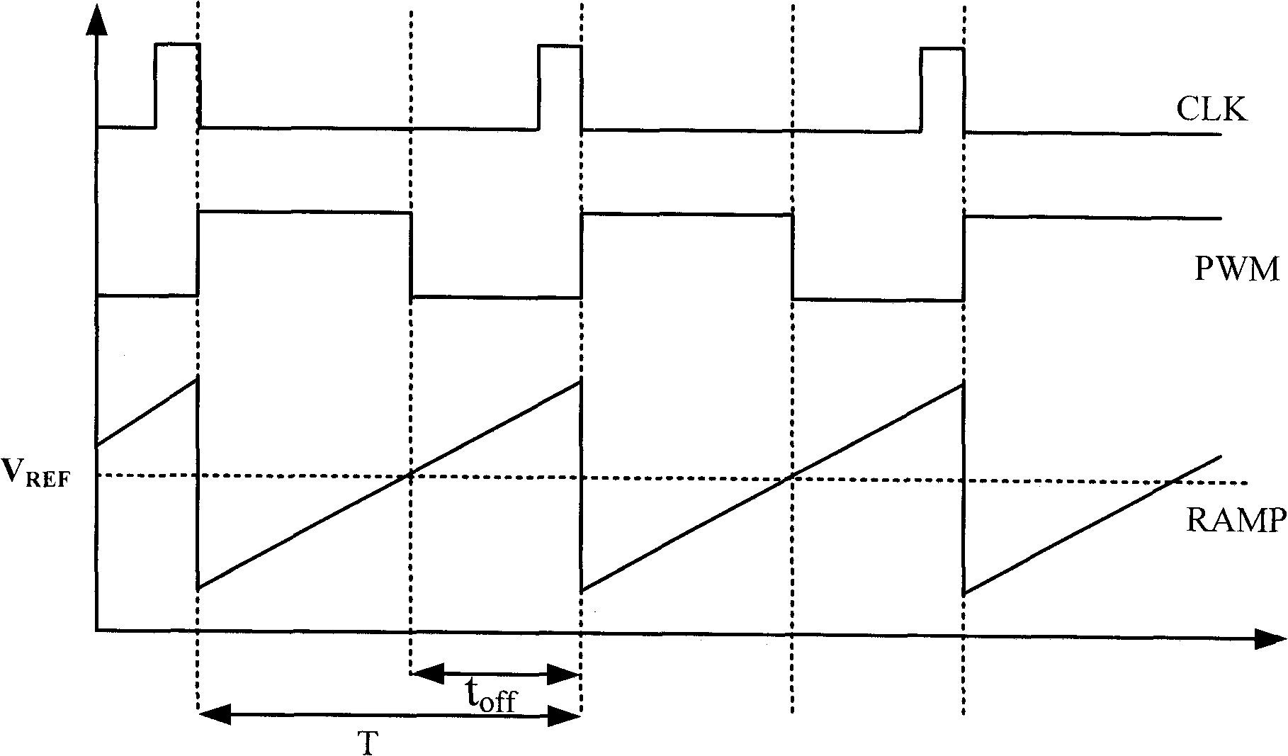
technical field [0001] The invention relates to a power conditioner, in particular to a power conditioner with a fixed-frequency constant-time control scheme and a control method thereof. Background technique [0002] In the implementation scheme of the power regulator in the prior art, the adjustment of the output voltage or current is mainly realized by controlling the turn-on and turn-off time of the switching device in the topology. Among them, there are mainly two control schemes for the control of switching devices, one is a PWM control scheme using a constant frequency, and the other is a constant time control scheme (which may include constant off-time and constant on-time control schemes). [0003] Figure 1A with Figure 1B Shown are the block diagram and operating waveforms of an example PWM control scheme with constant frequency. As shown in the figure, the basic working principle of the constant frequency PWM control scheme is that in each fixed switching cycl...

Claims


Application Information

Patent Timeline
Patent Type & Authority Applications(China)
IPC IPC(8): H02M3/155H02M1/44
CPCG05F1/10
Inventor 程帅
Owner SILERGY SEMICON TECH (HANGZHOU) CO LTD
Learn More