
Pneumatic tyre

A technology of pneumatic tires and tires, which is applied to tire parts, tire treads/tread patterns, transportation and packaging, etc. It can solve the problems of reducing the handling stability on dry roads, reducing drainage performance and traction performance, and may not be able to achieve it. Achieve the effects of improving handling stability, increasing rigidity, and suppressing front-to-back and sideways skidding

Active Publication Date: 2010-07-28
THE YOKOHAMA RUBBER CO LTD
View PDF4 Cites 28 Cited by
  • Summary
  • Abstract
  • Description
  • Claims
  • Application Information

AI Technical Summary

Problems solved by technology

According to such a tread pattern, although increasing the composition of the transverse grooves can improve the traction performance when driving on snow, it will also reduce the steering stability when driving on dry roads.
Moreover, narrowing a part of the lateral groove (for example, refer to Japanese Patent Laid-Open Publication No. 2004-345457), although it can improve the steering stability when driving on a dry road, it will reduce the drainage performance and reduce the water drainage performance when driving on snow. traction performance
[0003] Therefore, in recent years, it has been demanded, for example, that pneumatic tires for small trucks mounted on commercial vehicles can maintain good wet road performance including drainage performance, and improve traction performance and sideslip prevention performance including driving on snow. The handling stability when driving on snowy ground is also required to improve the handling stability when driving on dry roads, but these requirements may not be met at present

Method used


Image

  • Pneumatic tyre
  • Pneumatic tyre
  • Pneumatic tyre

Examples


Embodiment

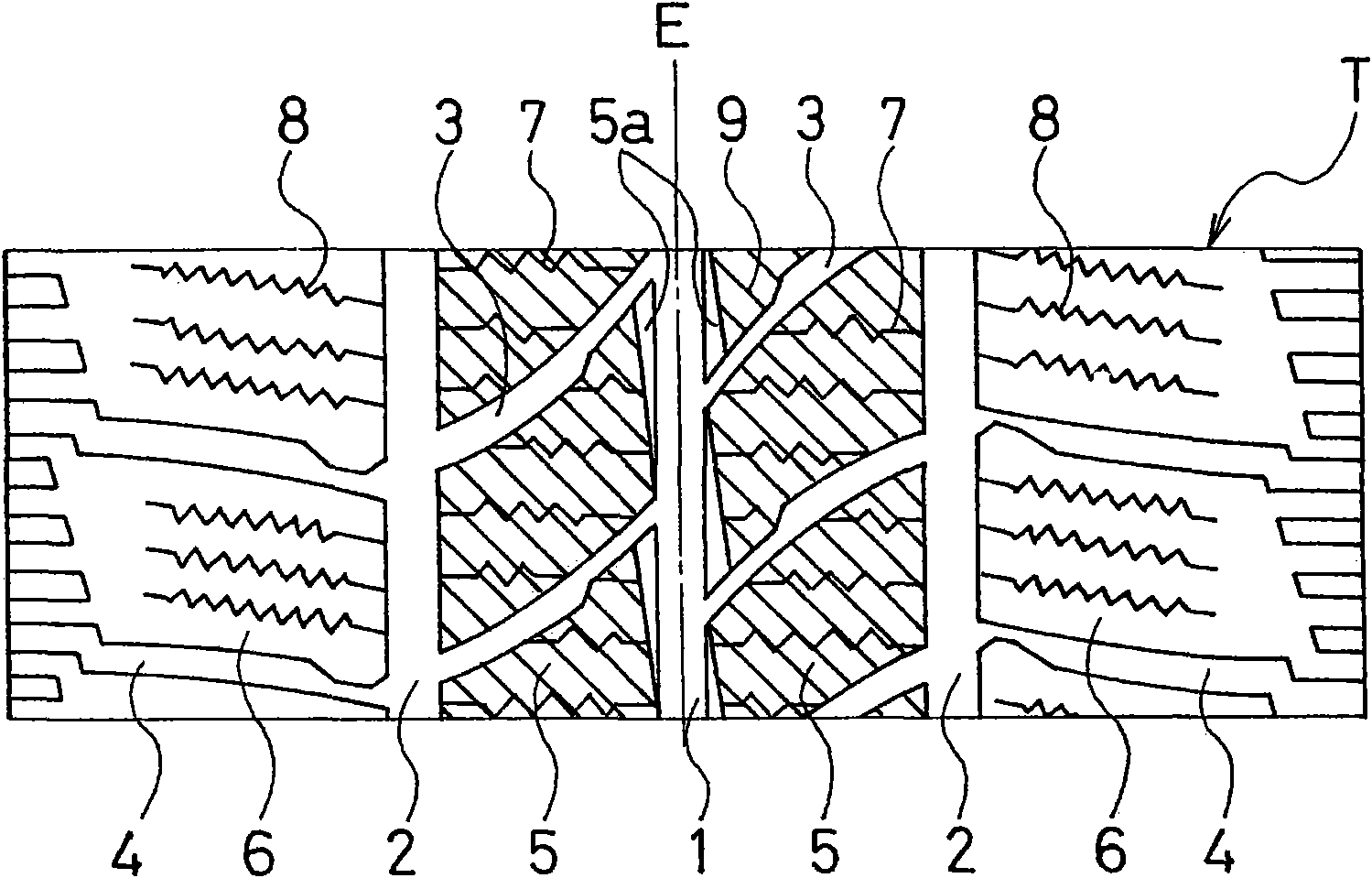
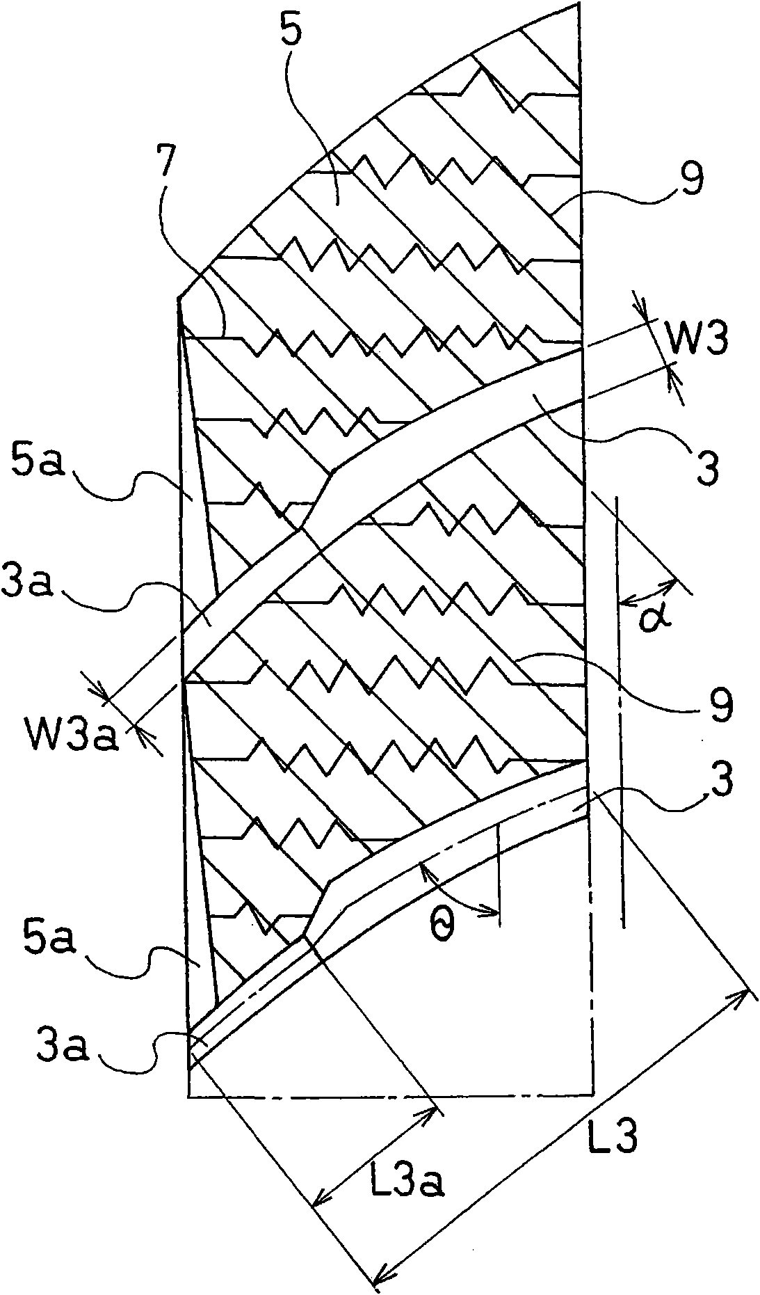
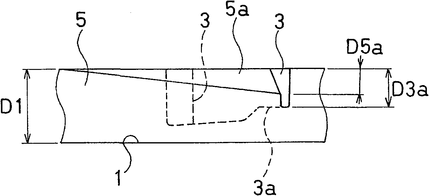
[0042] The tire size of the pneumatic tire is 195 / 75R16C, 107 / 105R, and the tread part is provided with three main grooves extending linearly in the tire circumferential direction and a plurality of transverse grooves extending in the tire width direction. The groove is divided into a plurality of pattern blocks, and a plurality of sipe patterns are arranged on each pattern block. As shown in Table 1, the inclination angle formed by the transverse groove and the tire circumferential direction, whether the transverse groove has a riser, whether there is a Chamfering, presence or absence of fine grooving, ratio of the minimum and maximum groove width of the transverse groove (W3a / W3×100%), ratio of the groove depth of the transverse groove in the ascending part to the groove depth of the central main groove (D3a / D1×100%), the ratio of the length of the rising portion to the length of the lateral groove (L3a / L3×100%), tires of Conventional Example, Comparative Examples 1-3 and Ex...


PUM


Abstract

The invention relates to a pneumatic tyre. At least three main grooves (1,2) extending towards the perimeter of the tyre and a plurality of horizontal grooves (3) extending towards the width direction of the tyre and communicating between the main grooves are mounted on a tyre tread part (T) and a plurality of pattern blocks (5) are divided using the main grooves (1,2) and the horizontal grooves (3), characterized in that: a central main groove (1) on a tyre equator (E) is formed into a straight line shape and the horizontal groove (3) is arranged and inclined by 40-60degree relative to the tyre perimeter and an ascending part (3a) is formed at the part of the horizontal groove (3) communicated with the central main groove (1) to make the groove width and the groove depth of the horizontal groove (3) proportionally change and the groove depth (D3a) of the horizontal groove (3) is 40-60% of the groove depth (D1) of the central main groove (1) and the minimum groove width (W3a) of the horizontal groove (3) is 30-50% of the maximum groove width (W3). The pneumatic tyre well keeps the wet road and simultaneously improves the operation stability during driving on the snow road and the dry road.

Description

technical field [0001] The present invention relates to a pneumatic tire suitable for small trucks, in particular, to a pneumatic tire capable of maintaining good performance on wet roads and simultaneously improving handling stability when driving on snow and driving stability when driving on dry roads. Pneumatic tires. Background technique [0002] In a pneumatic tire, at least three main grooves extending in the tire circumferential direction and a plurality of transverse grooves extending in the tire width direction are provided on the tread portion, and a plurality of blocks divided by these main grooves and transverse grooves are used. tread pattern. According to such a tread pattern, although increasing the composition of the lateral grooves can improve the traction performance when running on snowy ground, it also lowers the steering stability when running on a dry road surface. Moreover, narrowing a part of the lateral groove (for example, refer to Japanese Patent...

Claims


Application Information

Patent Timeline
Patent Type & Authority Applications(China)
IPC IPC(8): B60C11/11
CPCB60C2011/1231B60C2011/1213B60C11/1392B60C2011/0369B60C11/12B60C11/0306B60C2011/0372
Inventor 永吉胜智
Owner THE YOKOHAMA RUBBER CO LTD
Learn More