
Compact hydraulic accumulator

一种蓄能器、缸体的技术,应用在执行器蓄能器、流体压力致动装置、运输和包装等方向,能够解决没有提供保护套筒完整性、高昂、不能进行维修等问题

Inactive Publication Date: 2010-07-14
LIMO REID INC
View PDF9 Cites 11 Cited by
  • Summary
  • Abstract
  • Description
  • Claims
  • Application Information

AI Technical Summary

Problems solved by technology

[0007] 2. High-pressure accumulator design in the prior art
Third, this design cannot be repaired - any failure of any component requires scrapping the entire block
Fifth, this design provides no means of protecting the integrity of the sleeve in case the fluid pressure exceeds the gas pressure
Prior art metal bellows accumulators are not durable enough under stress
All types of prior art piston accumulators are unacceptably heavy and costly
Accordingly, the prior art fails to provide a high pressure accumulator suitable for hydraulic hybrid motor vehicle applications as required for the present invention

Method used


Image

  • Compact hydraulic accumulator
  • Compact hydraulic accumulator
  • Compact hydraulic accumulator

Examples


Embodiment Construction

[0035] The following description is merely exemplary in nature, and is not intended to limit the disclosure, application or uses. It should also be understood that throughout the drawings, corresponding reference numerals indicate like or corresponding parts and features. With respect to the disclosed methods, the order of the steps presented is exemplary in nature, and thus not required or critical.

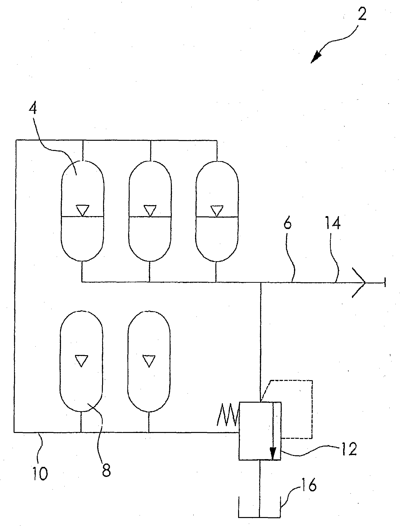
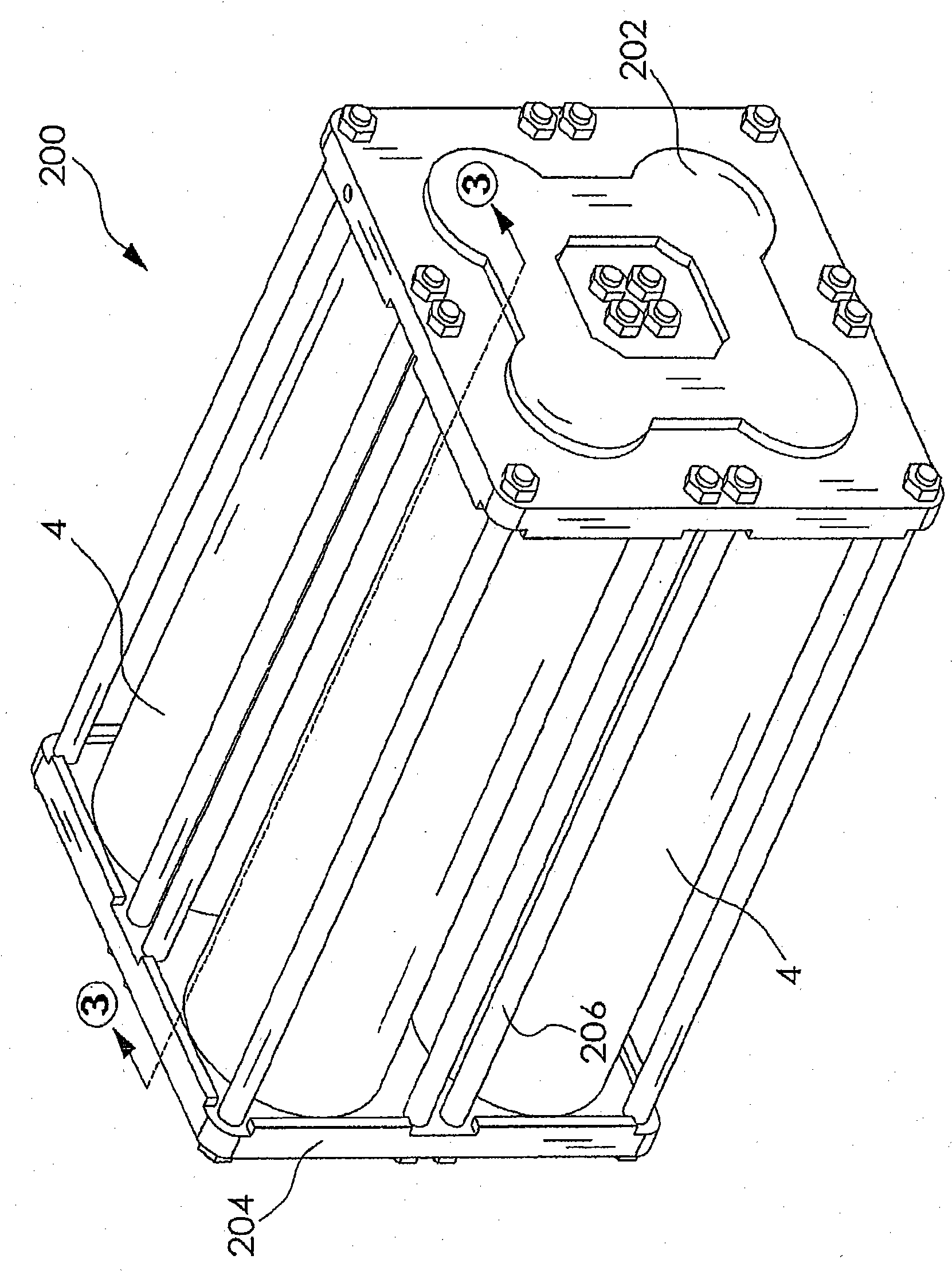
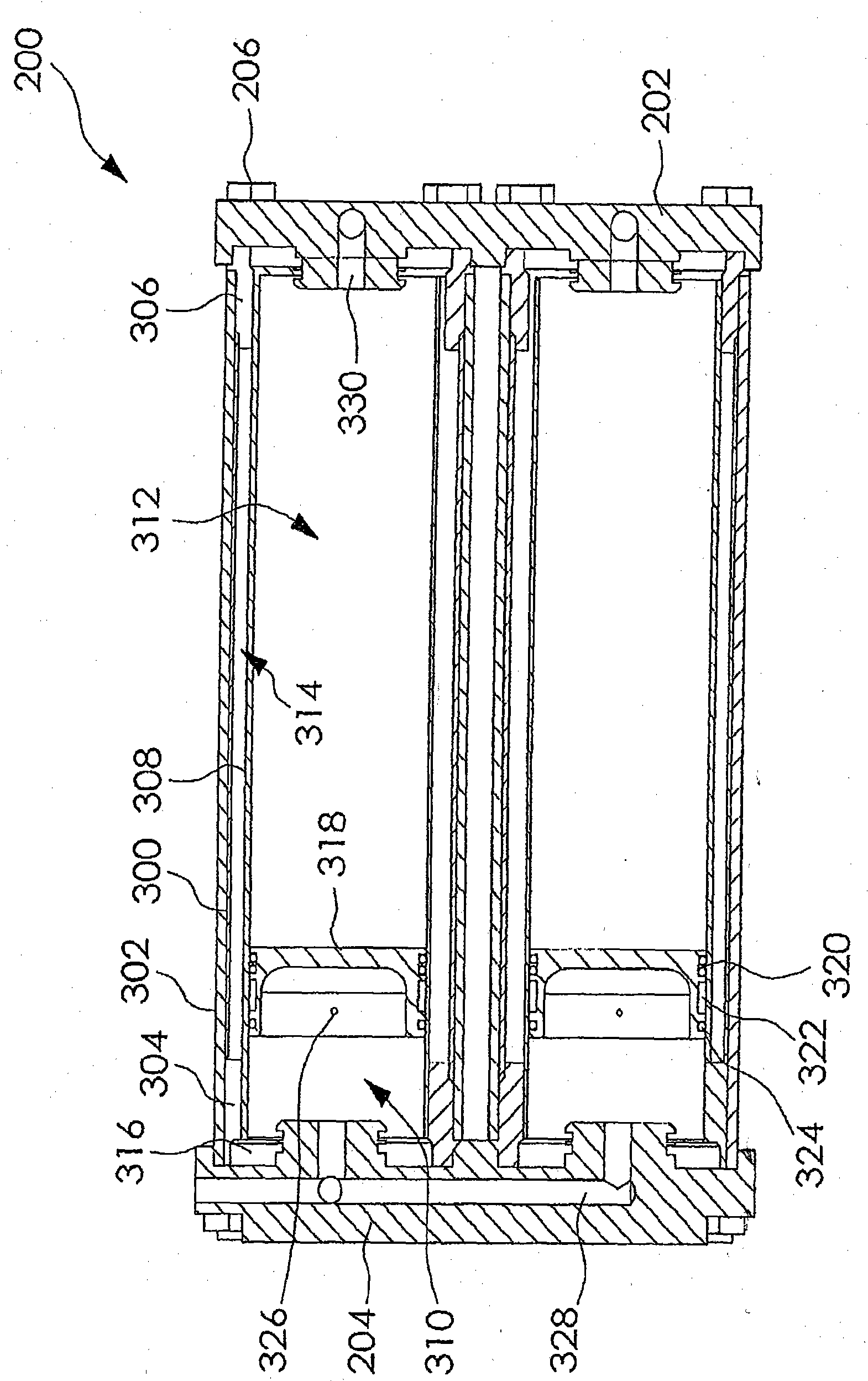
[0036] figure 1 An overall schematic diagram of the accumulator system 2 is shown in . The accumulator system 2 comprises at least one accumulator cylinder 4, whose fluid side connection is connected to a common fluid network (fluidnetwork) 6; zero or more auxiliary gas cylinders 8, whose gas side connection is connected to the accumulator The cylinders 4 share a common gas grid 10 ; and a gas-mediated differential pressure relief valve 12 . The accumulator system 2 is coupled on the main hydraulic circuit by a connector 14 and the pressure relief valve 12 has a connection to...


PUM


Abstract

A lightweight, optimally efficient, easily serviced, piston-in-sleeve high pressure accumulator is provided. The accumulator includes one or more cylindrical composite pressure vessel separate end cap manifolds. A piston slidably disposed in a thin impermeable internal sleeve in the accumulator separates two chambers, one adapted for containing a working fluid and the other adapted for containing gas under pressure. Gas is provided in a volume between the impermeable internal sleeve and the composite pressure vessel wall. Additional gas is optionally provided in gas cylinders. Further components are provided for withstanding harmful effects of radial flexing of the composite vessel wall under high pressures, and from stresses present in use in mobile applications such as with a hydraulic power system for a hydraulic hybrid motor vehicle.

Description

[0001] Cross References to Related Applications [0002] This application claims the benefit of US Provisional Application No. 60 / 943,930, filed June 14, 2007. The entire disclosure of the aforementioned application is incorporated herein by reference. technical field [0003] The present disclosure relates generally to accumulators for high pressure applications, and more particularly to high pressure accumulators of the piston-in-sleeve (or "piston and sleeve") type. The present disclosure also relates to the potential use of such accumulators in connection with fuel efficient hydraulic hybrid motor vehicles. Background technique [0004] 1. Hydraulic hybrid vehicles [0005] Hybrid powertrains are an increasingly popular approach to improving the fuel efficiency of motor vehicles. The term "hybrid" refers to the combination of a conventional internal combustion engine with an energy storage system typically used to receive and store excess energy produced by the engine...

Claims


Application Information

Patent Timeline
Patent Type & Authority Applications(China)
IPC IPC(8): F15B1/24
CPCF15B2201/32F15B1/24F15B2201/205B60K6/12F15B2201/31F15B2211/212F15B2211/50518Y02T10/6208F15B2201/4056Y10T137/7837Y02T10/62
Inventor J·A·奥布赖恩R·赫布斯G·罗斯顿
Owner LIMO REID INC
Learn More