
Construction method for pouring after settlement of reinforced concrete continuous beam with cohesive pre-stress

A technology of reinforced concrete and bonded prestressing, which is applied to the processing of formwork, processing of building materials, and preparation of building components on site. simple effect

Inactive Publication Date: 2010-07-14
BEIJING SHOUGANG CONSTR GROUP
View PDF0 Cites 17 Cited by
  • Summary
  • Abstract
  • Description
  • Claims
  • Application Information

AI Technical Summary

Problems solved by technology

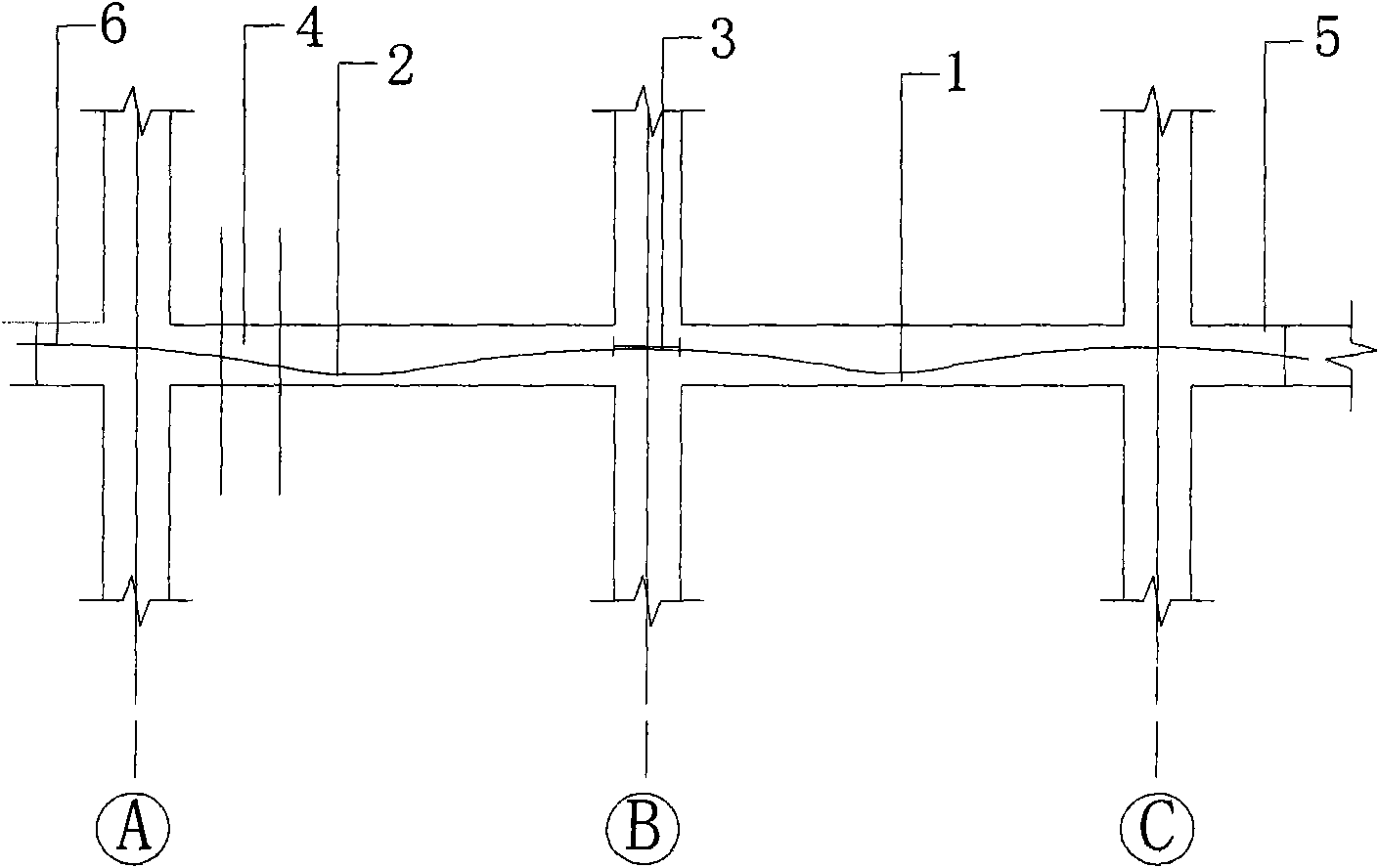
[0003] The object of the present invention is to provide a kind of construction method that has bonded prestressed reinforced concrete continuous girder subsidence poured belt, has overcome existing reinforced concrete continuous beam when there is postcast belt and meets bonded prestress, cannot Unified removal of the supporting scaffolding in this area; this construction method can not only stretch the prestressed reinforced concrete cast-in-place beam with one span after pouring without settlement in advance, remove the scaffolding in this area in advance, and insert it into the next construction process in advance, but also ensure The structure on the side of the cast belt after settlement meets the stress requirements

Method used


Image

  • Construction method for pouring after settlement of reinforced concrete continuous beam with cohesive pre-stress
  • Construction method for pouring after settlement of reinforced concrete continuous beam with cohesive pre-stress
  • Construction method for pouring after settlement of reinforced concrete continuous beam with cohesive pre-stress

Examples


Embodiment Construction

[0020] Figure 1 to Figure 5 It is a specific embodiment of the present invention.

[0021] exist figure 1 In the process, after the concrete strength reaches the tensile strength, stretch the prestressed steel bar 1, remove the support system at this place, and reserve the early demolition support system at the tensioned steel bar 2; For the concrete poured with the belt, after the strength of the concrete poured with the belt reaches the tensile strength after settlement, the second prestressed steel bar 2 is stretched, and the supporting system at this place is removed.

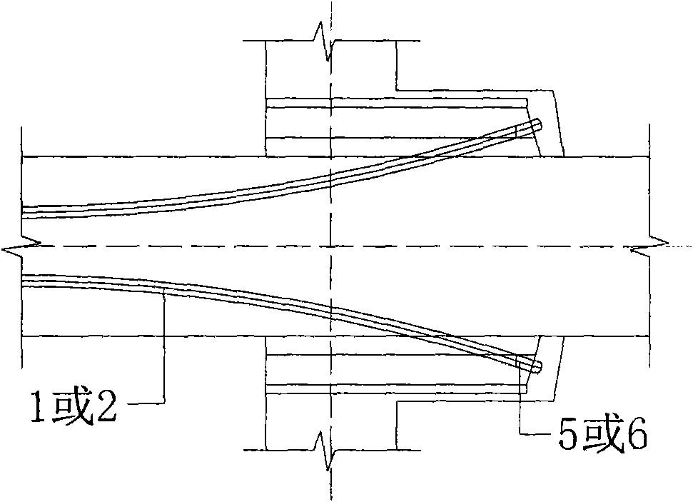
[0022] exist figure 2 In , tension bar 1 and tension bar 2 are overlapped through beam haunches at beam haunch tension end 5 and beam haunch tension end 6.

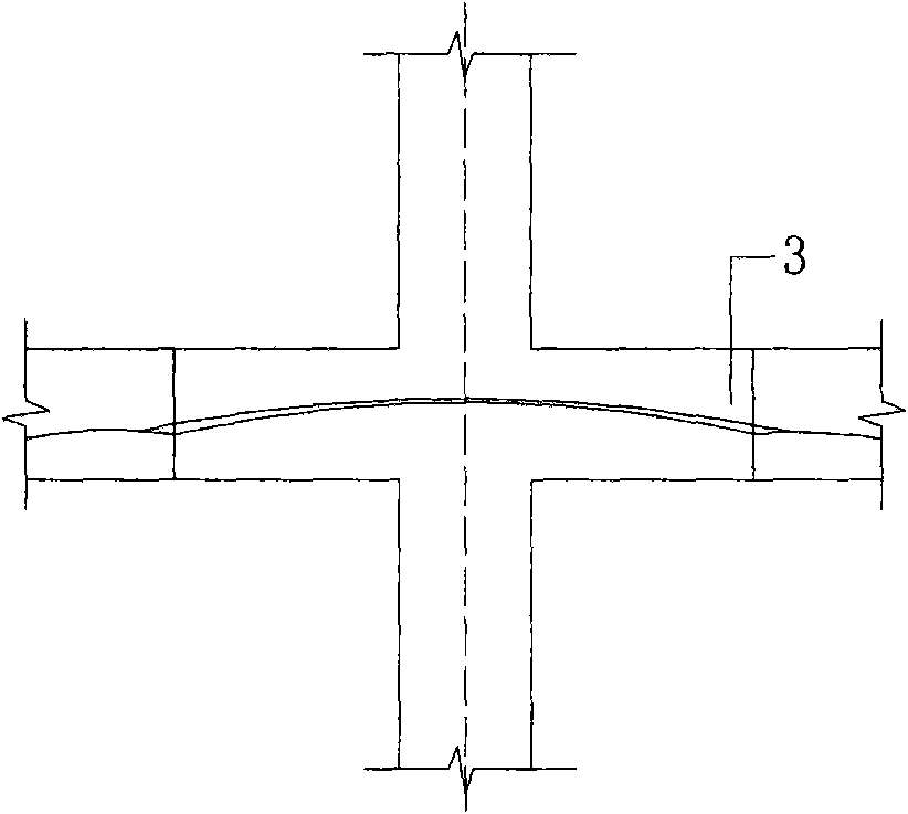
[0023] exist Figure 4 In the above, the tensioned first prestressed steel bar 1 and the tensioned second stressed steel bar 2 are lapped at the prestressed steel bar overlap 3 through the beam haunch. The application of the construction method ...


PUM


Abstract

The invention relates to a construction method for pouring after the settlement of reinforced concrete continuous beam with cohesive pre-stress, which belongs to the technical field of reinforced concrete construction. The template construction of a primary beam, a secondary beam and a floor slab of a reinforced concrete frame structure adopts an early dismantling system framework; the pre-stressed reinforced concrete of the main beam is erected on two spans of brackets, and respectively meets the erection requirements; the tension ends on both sides of the two spans are respectively provided with beam haunches on both sides of the brackets; the beam haunches are respectively designed into the tension ends; pres-stressed reinforced concrete and cast concrete are paved according to the design requirements; after the concrete of the main beam reaches 14 days and 80percent of design strength, the pre-stressed beam on the right side is tensioned; after tensioning, the template early dismantling supporting scaffold of the span is dismantled; the early dismantling system supporting scaffold at the bottom of the pre-stressed beam on the left side is not dismantled, and the concrete at the settled pouring part after settlement is poured after structural settlement, and micro expansion concrete is used to cast the settled poured belt; and after the poured belt concrete after the main beam reaches 14 days and 80percent of design strength, the pre-stressed beam of the span on the left side is tensioned. And the construction method has the advantages of lower construction cost and simple process.

Description

technical field [0001] The invention belongs to the technical field of reinforced concrete construction, and in particular relates to a construction method for a post-settlement poured belt of a bonded prestressed reinforced concrete continuous beam, especially a bonded prestressed reinforced concrete continuous beam with a post-settlement poured belt left in a complex environment with a large space and a large span. In prestressed continuous beams. Background technique [0002] At present, there are not many known situations in which reinforced concrete continuous beams have both post-cast strips and bonded prestressing in general. Once this situation is encountered, the conventional construction method is to support the scaffolding in the area of ​​the prestressed beam. After the settlement of the post-casting belt meets the requirements, the concrete construction of the post-casting belt and the tensioning of the prestressed steel bars will be carried out. Finally, the su...

Claims


Application Information

Patent Timeline
Patent Type & Authority Applications(China)
IPC IPC(8): E04G21/02E04G21/12E04G19/00
Inventor 白少辉韩宝进王志鹏尹宝华柳俊民于志强刘飞
Owner BEIJING SHOUGANG CONSTR GROUP
Learn More